

How to simplify a CAD model before sharing it
A supplier usually needs interfaces, clearances, and a trustworthy envelope, not your complete assembly history. Build a separate derivative around that job and prove what survived before sending it.
Quick answer
Simplify a CAD model for sharing by creating a separate derivative from the released master, keeping only the interfaces, envelopes, datums, and properties the recipient needs. Remove internal parts, design history, and unnecessary metadata, then reopen the exported file and validate fit, clearance, motion, and revision identity against the master.
The supplier asks for the native assembly at 4:38 on Friday. The review call is still open, the workstation fan has started its impression of a vacuum cleaner, and the section view on the second monitor shows the gearbox internals, custom fasteners, and three years of design history. They need four mounting holes and the space around an output shaft. Sending everything would be quicker, in the same way leaving the front door open is quicker than finding your keys.
Create a separate, purpose-built derivative instead. Use defeaturing to keep the mounting interfaces, connection geometry, external envelope, datums, keep-out zones, and properties the recipient actually needs. Remove internal components, unnecessary features, history, and metadata. Then reopen the delivered file and prove that it still answers the recipient's question.
Do not simplify the master model. Do not assume a smaller file is automatically safe. The useful target is minimum necessary geometry with enough engineering evidence left to do the agreed job.
Start with the recipient's job#
“Send us a simplified model” is not a specification. A machine builder placing your gearbox needs different geometry from a foundry quoting its housing or a service technician checking tool access.
Write the receiving task down before touching the model:
| Receiving task | Geometry and data that normally matter | Detail that may be unnecessary |
|---|---|---|
| Layout and space claim | External envelope, travel envelope, mounting position, connector and service keep-outs | Gears, bearings, internal fasteners, feature history |
| Mating-part design | Mounting faces, hole axes, pilot diameters, shaft or port geometry, coordinate system | Unrelated internals and cosmetic features |
| Interference check | Accurate outer shape, moving positions, cable and tool envelopes | Hidden mechanisms that never affect the checked volume |
| Manufacturing quote | Complete part geometry, material, tolerances, finish, and revision | Other assembly components and company-only metadata |
| Rendering or sales layout | Recognisable exterior and colours, if approved | Exact internal geometry and manufacturing annotations |
The manufacturing row is deliberately awkward. A supplier making the part cannot quote or manufacture from a rough envelope. For that job, aggressive simplification is the wrong tool. Send the controlled part definition under the correct commercial and data controls instead of pretending a rounded box is manufacturing data.
 A complex assembly contains far more information than every downstream task needs. Source: PTC's large-assembly guidance.
Defeaturing changes the deliverable#
Hiding a component changes a view. Suppressing a component changes an assembly state. Defeaturing creates geometry with detail removed or replaced. Those are not interchangeable operations.
SOLIDWORKS Design Help 2026 says its Defeature tool can remove detail from parts and assemblies and save a new file where the result is made from solids without feature definition or history. Its Simplify Geometry method removes selected components and details; its Silhouette method builds a simplified part from component and body outlines.
That distinction is useful. Simplify Geometry is selective. Silhouette is more like replacing a cupboard full of parts with the outside of the cupboard. The second approach can be excellent for layout and IP reduction, but it is a poor choice when a mounting recess, connector latch, or service opening carries the actual interface.
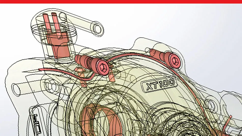 SOLIDWORKS presents silhouette defeaturing as a way to simplify an assembly for sharing and reduce exposed design detail. Source: SOLIDWORKS.
The official SOLIDWORKS demonstration shows silhouette groups replacing detailed assembly geometry. Source: SOLIDWORKS on YouTube.
Make an interface list before removing anything#
The safest workflow is subtraction from an approved list, not deletion until the file feels light enough. For a purchased motor, pump, actuator, or gearbox, I would record these items first:
- Mounting faces, bolt patterns, pilot features, and locating datums.
- Input and output axes, shaft extents, port threads, and connector engagement volumes.
- The static envelope plus every travel, bend, cooling, guarding, and tool-access keep-out.
- Mass, centre of gravity, and inertia only when the receiving analysis actually needs them.
- Units, coordinate system, orientation, part number, revision, and the intended use of the derivative.
- Any face or datum the recipient will select for a mate, dimension, measurement, or downstream check.
This list becomes the acceptance test. If the recipient needs to mate to a pilot diameter, a bounding box is not enough. If the job is only floor-layout planning, sending the bearing seats is pointless exposure.
The CAD assembly interference guide explains the other side of this decision. A simplified motor cylinder may be fine for a space claim and useless for connector access. The check determines the geometry that must remain.
Shrinkwrap is a derivative, not the master wearing a disguise#
Creo's shrinkwrap model is a useful example of a deliberate derivative. Creo 12 Help describes a shrinkwrap model as a separate part made from a collection of surfaces representing a source model's exterior. It can close holes, control detail, carry selected datums, use exact mass properties from the source, and export to formats including STEP and IGES.
The same page makes an important release point: a shrinkwrap model is not associative. It does not update when the source changes. That is good for separating a delivery file from live design references, but it creates an obvious obligation. Every new master revision needs the derivative regenerated and checked again.
 PTC's shrinkwrap example reduces an assembly to the exterior information needed by a lighter downstream model. Source: PTC.
Keep the simplified file beside the master in the same release process. Name its purpose in the filename or metadata, such as GEARBOX-R12-LAYOUT-ENVELOPE, and record which master revision generated it. “Final-small.step” is how perfectly intelligent people end up measuring the wrong model six months later.
Automation makes consistency possible, not correctness#
Autodesk's Inventor 2026 developer note says the 2026 release added official API access to the existing Simplify feature. Its sample can replace geometry with envelopes, remove internal bodies, and remove bodies below a size threshold. That makes batch processing and repeatable rules possible.
It also makes a bad rule repeatable. A “remove every body under 10 cm” rule cannot know that one small connector is the only feature the customer needs. Rule sets should begin with a stated receiving task, preserve named interfaces, and produce a report of what they removed.
Autodesk Inventor's official demonstration shows parts, features, and internal detail being removed or replaced by envelopes. Source: Autodesk Inventor on YouTube.
For recurring supplier packages, automation is worth considering when the same product family needs the same derivative every release. Run the script from the controlled master, keep the rules under change control, and make validation fail loudly when a required face, datum, or property disappears.
File format decides what crosses the boundary#
A simplified native file may still contain configurations, properties, references, thumbnails, or application-specific data you did not mean to send. A neutral file usually removes the native recipe, but it does not make the remaining shape vague or unmeasurable.
STEP and Parasolid can carry exact B-Rep surfaces. That is useful for mating-part design and interference checks, and it means every exterior feature you leave can be measured and copied. A faceted mesh removes exact analytic surfaces but can also make accurate mating and clearance work worse. Converting good geometry into triangles is not a serious access-control system.
Use the CAD file-format guide to choose the downstream representation. Then inspect the exported file for:
- hidden or suppressed bodies that unexpectedly returned;
- part names, custom properties, materials, and author fields;
- drawings, PMI, configurations, and embedded previews;
- external references, cloud links, and paths to internal files;
- units, axes, and assembly structure the recipient needs.
The recipient should get enough semantic information to use the derivative correctly, but not a grab bag of whatever the export dialog happened to include.
A gearbox handoff example#
Suppose a machine builder needs to place a gearbox and design its mounting bracket. The full assembly contains gears, bearings, shafts, seals, fasteners, lubrication passages, and proprietary housing features.
The layout derivative should keep the mounting face, pilot, bolt-hole axes, output-shaft envelope, connector envelope, service clearances, and the overall housing shape. It may need mass and centre of gravity for a moving-axis calculation. It does not need the tooth geometry, bearing construction, internal fasteners, or feature tree.
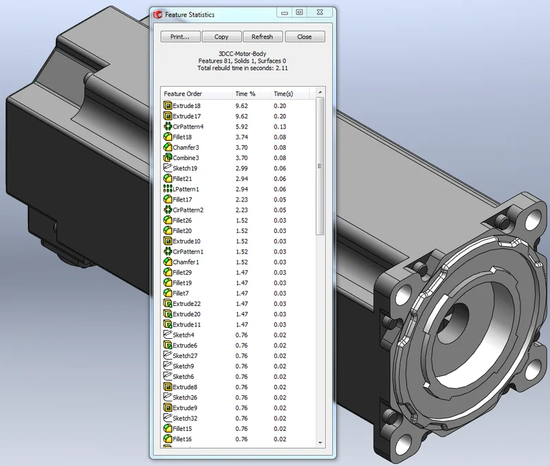 A SOLIDWORKS motor example shows why a downstream layout can need the mounting holes while not needing every internal component. Source: SOLIDWORKS Blog.
Compare the derivative with the master at the interface list. Measure hole positions and shaft extents from the agreed datum system. Run a bounding-box or volume comparison for the external shape. Check the bracket mate and required clearance in the receiving assembly. If mass matters, compare the carried value with the released source and label whether it is copied or recalculated from the simplified solid.
No CAD model was simplified or reverse-engineered for this guide. The product behaviours come from the current SOLIDWORKS 2026, Creo 12, and Inventor 2026 sources linked above. The handoff method is an engineering interpretation of those documented tools, not proof that defeaturing makes a design impossible to reconstruct.
Validate the package from the outside#
Open the delivered file in a clean project or, preferably, the receiving CAD system. Do not validate only inside the master session that created it.
- Confirm the filename, part number, revision, units, and intended-use note.
- Reopen the export and check that it contains no unexpected bodies, references, properties, or documents.
- Measure every retained interface from the agreed datums.
- Check space claim, interference, motion, and access using the derivative itself.
- Compare mass properties only when they are part of the agreed package.
- Confirm that removed internals cannot be recovered by changing a configuration, unsuppressing a body, or following an external reference.
- Store the derivative and its check record against the same engineering revision as the master.
- Send through the approved transfer and access process. Geometry reduction does not replace permissions, contracts, or export-control review.
The CAD version-control workflow matters because the simplified model is another release artifact, not a disposable attachment. When the master changes, the derivative becomes stale even if its filename still says final.
Good defeaturing is a contract about what remains. Keep the interfaces that let the other person do their job, remove the geometry and history they do not need, and prove the derivative in the system where it will be used. A small file is pleasant. A small file that still tells the truth is the actual result.
Related articles
CAD Workflows
Large CAD assemblies: make them faster without losing trust
Speed up a large CAD assembly by measuring which work is slow, reducing unnecessary mate solving and feature regeneration, and using task-specific lightweight or simplified representations. Keep the full released model authoritative, and restore it for interference, mass, drawing, export, and manufacturing checks.
CAD Workflows
CAD assembly interference checks: what a clean result misses
Run interference detection on the exact released assembly to find overlapping nominal solids, then check minimum clearance and collision through every critical motion. A clean static result does not prove tolerance-safe fit, room for movement, flexible-part behaviour, or manufacturing readiness.
CAD Workflows
Text-to-CAD file formats: STEP, Parasolid, STL, 3MF, and more
Use the native CAD file when both people use the same system, Parasolid when both systems share that kernel, and STEP AP242 for the safest neutral engineering handoff. Use 3MF for printing, glTF or GLB for browser review, and DXF for flat 2D profiles.
Newsletter
Get new CAD articles in your inbox
Text-to-CAD guides, new tools, CAD comparisons, and practical tutorials.