

Direct vs parametric modeling: choose for the change
Direct modeling is quick when geometry arrives without history. Parametric modeling earns its keep when the next revision must preserve intent, relationships, and a family of controlled changes.
Quick answer
Use direct modeling for local edits to imported geometry, fast concepts, and changes whose intent is obvious from the existing faces. Use parametric modeling when dimensions, relationships, configurations, drawings, and future revisions must update predictably; most production workflows benefit from mixing both deliberately.
The supplier file lands at 4:47 on Friday with one hole in the wrong place. It opens as a single imported body, the review call starts in thirteen minutes, and the coffee beside the cheap mouse has already gone cold. Rebuilding the part from sketches would be responsible, slow, and slightly ridiculous for a 6 mm shift. Dragging the cylindrical faces into place feels almost too easy.
That is the useful dividing line. Use direct modeling when the change is local, the intended result is clear from the geometry, and no usable construction history exists. Use parametric modeling when the next change must preserve dimensions, relationships, configurations, drawings, or a family of parts. In real work, the sensible answer is often a controlled hybrid: keep important intent in history, then use a direct edit where rebuilding half the tree would add risk rather than remove it.
The method should follow the change. CAD arguments get silly when they turn two useful tools into rival religions.
The difference is history, not whether you drag a face#
Parametric modeling records an ordered recipe. A constrained sketch drives an extrusion, that extrusion supplies an edge to a fillet, and the fillet becomes an input to something farther down the tree. Change a driving value and the program rebuilds that recipe.
Direct modeling changes the existing boundary representation without consulting the recipe that created it. Shapr3D's technical explanation defines it as editing a B-rep without using parametric history. A move-face operation detaches selected faces, moves their underlying surfaces, extends or trims neighbouring faces, and stitches the result back into a closed body. That is more involved than pushing pixels around, even when the interface makes it feel like dragging a drawer shut.
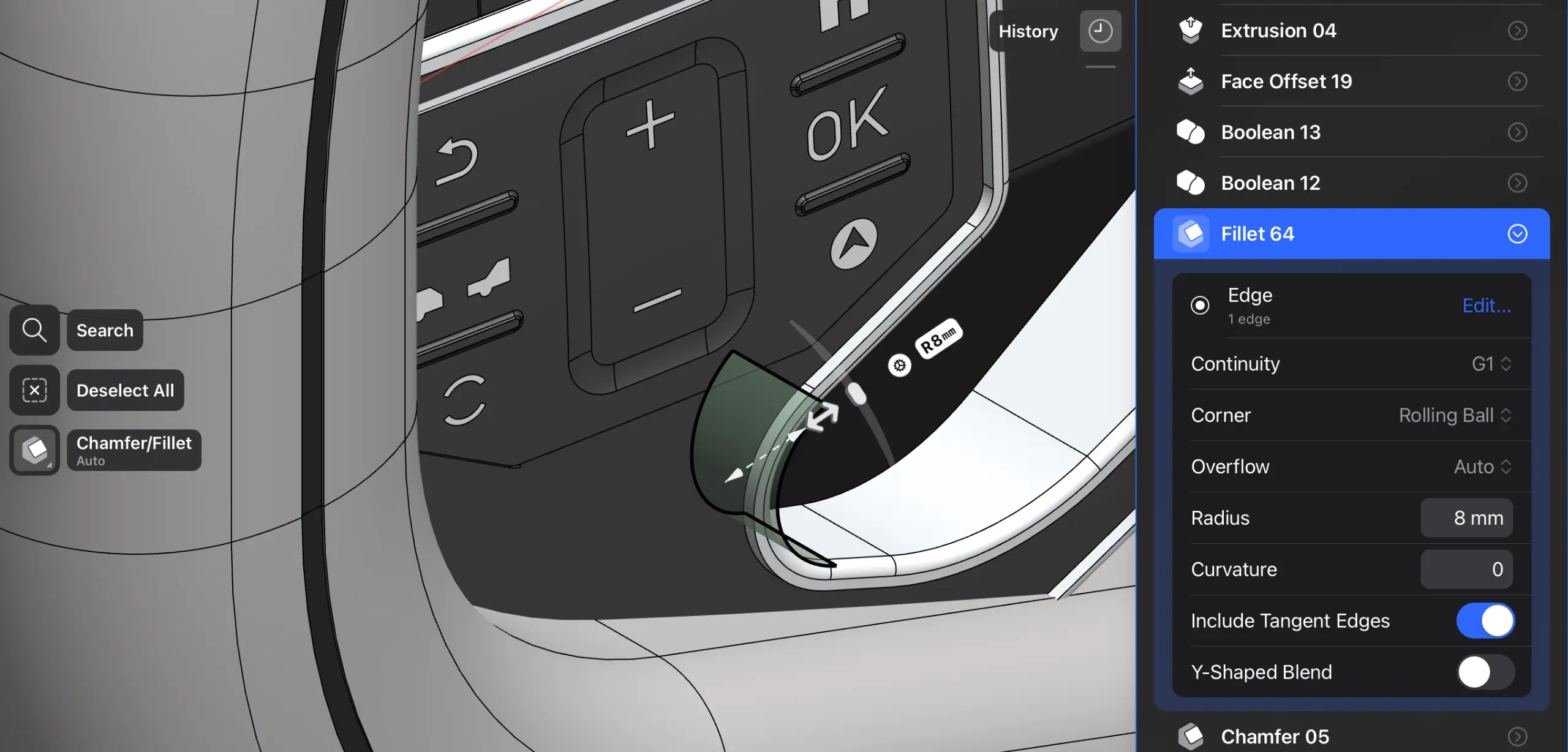 Shapr3D records the fillet and its parameters in the model history. Source: Shapr3D's history-based modeling guide.
The interaction is not the definition. A parametric program can record a face move as a feature. A direct modeler can ask for exact dimensions. The practical question is whether the change depends on an editable chain of earlier decisions.
Choose from the revision you expect next#
The first version of a part is a poor judge of a modeling strategy. Both methods can make a clean bracket. The difference appears after the client changes the mounting pattern, the supplier swaps a motor, or your past self leaves a feature tree that looks like tangled cables.
| Likely work | Better starting method | Why |
|---|---|---|
| A supplier STEP needs one hole moved | Direct | The file has no native history, and the local geometric intent is clear |
| A product family shares width, hole spacing, and wall thickness | Parametric | Named parameters and constraints can drive repeatable variants |
| A concept is changing shape during a review | Direct | Fast face edits communicate the change before the structure is settled |
| A drawing and downstream features must follow an interface dimension | Parametric | Associative references can update together when the driving value changes |
| A late fillet edit would break fragile upstream references | Hybrid | A recorded direct edit near the end of the tree may isolate the change |
| An imported part needs broad design-intent changes | Rebuild or obtain native data | A pile of face moves can hide the reason the part has its shape |
Parametric history pays for itself when you can name the future variable. If the part is a plate whose width, bolt pitch, and edge distance will produce twelve controlled sizes, encode those relationships. If the request is “move this boss until the cable clears,” a local direct edit may be the more honest description of the decision.
Parametric models make intended changes cheap#
A useful parametric model says more than “this face is here.” It says the slot remains centred, the holes stay equal, the wall follows the shell thickness, and the flange moves when the interface plane moves. Constraints and feature order turn those decisions into a model that can be regenerated.
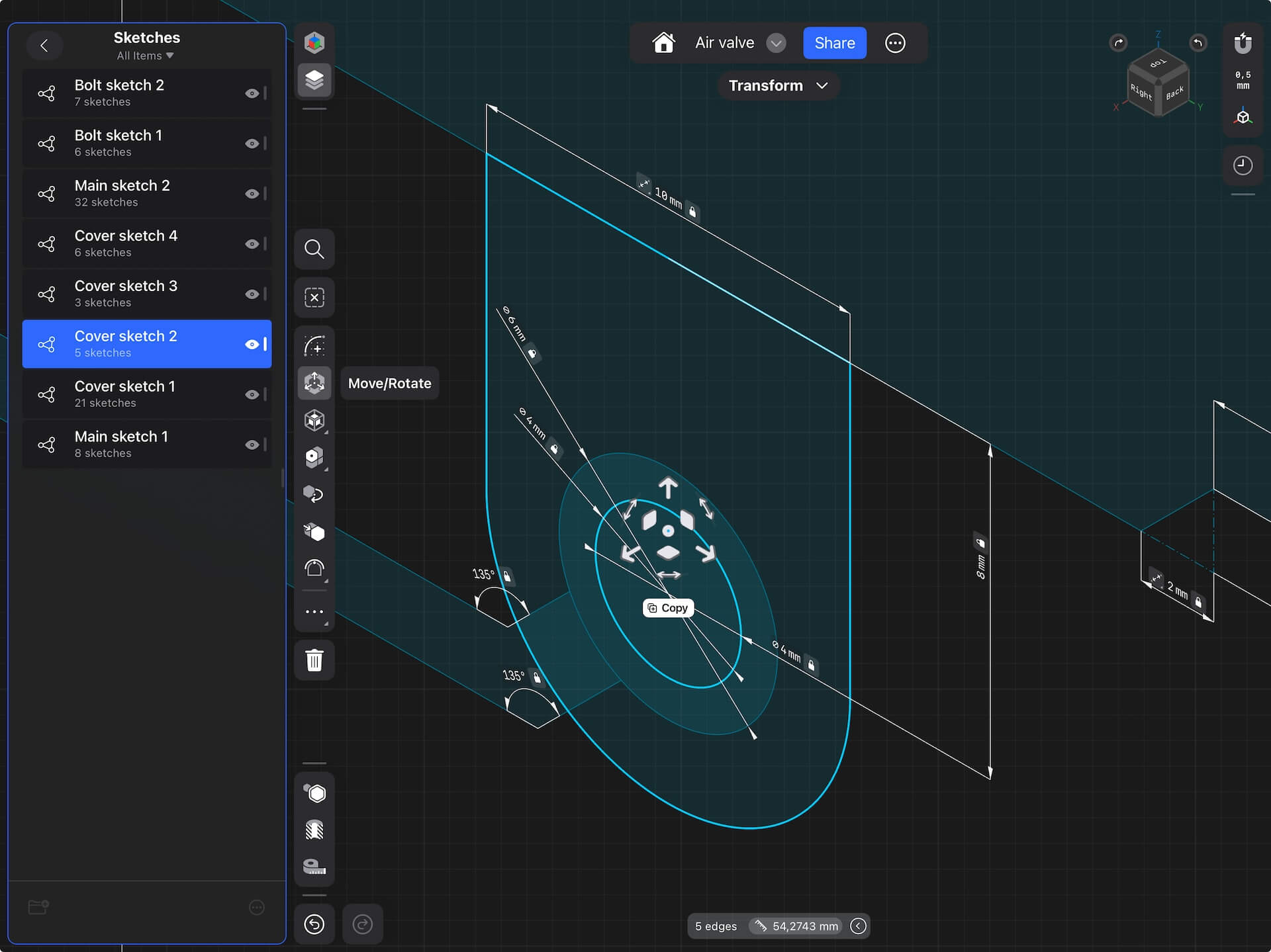 Connected sketches and dimensions make the intended relationships editable. Source: Shapr3D's history-based modeling guide.
Onshape's constraint documentation describes geometric constraints that maintain relationships such as coincidence, tangency, and equality. Those relationships matter when the geometry changes. A hole that merely happens to be centred today is not the same as a hole constrained to remain centred tomorrow.
History also supports audit and reuse. A teammate can inspect the feature list, a configuration can change a defined group of parameters, and an associative drawing can follow a revised model. None of that guarantees a good tree. References can break, rebuild time can grow, and a clever chain of dependencies can become incomprehensible to the next person.
I prefer a short tree with obvious driving sketches over a cathedral of flexibility nobody requested. The goal is controlled change, not the largest possible collection of parameters.
Shapr3D's official comparison shows both methods in the same solid-modeling environment. Source: Shapr3D on YouTube.
Direct modeling makes unplanned changes cheap#
Direct tools are at their best when the model has geometry but no trustworthy recipe. That is the normal state of a STEP file from another CAD system. The original sketches, constraints, feature names, and design intent did not travel with the solid.
Modern direct operations can move or offset faces, remove holes, change recognised blends, and replace one face with another. They work from the shape that exists now. You do not need to discover whether the original cylinder came from an extrusion or a revolve before changing its diameter.
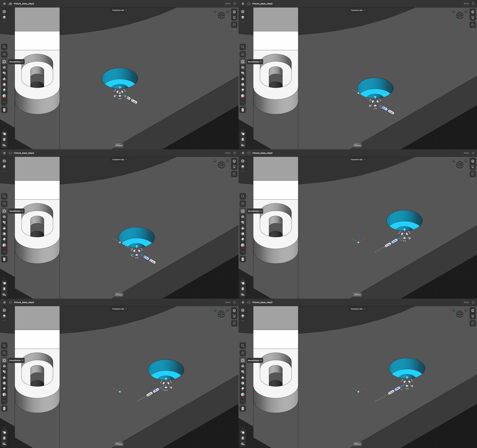 A face move changes the imported fixture directly, without reconstructing its original feature tree. Source: Shapr3D's explanation of direct modeling.
That freedom has a hard boundary. The kernel only sees the remaining surfaces and topology. It does not know that four holes were meant to form a pattern, that a boss must remain concentric with a bearing seat, or that a deleted rib carried a load. Shapr3D's source shows direct edits failing when large fillets remove the faces the kernel would need to extend. It also warns that stacking many direct operations can create another hard-to-change model.
Direct modeling is not careless modeling. It is geometry-first modeling, which means the engineer has to carry the intent somewhere else when the geometry cannot express it.
A hybrid model needs a visible boundary#
Current systems blur the old division. Shapr3D says its direct face edits appear as history steps. Fusion can put existing direct geometry into a Base Feature, then record later parametric operations in the Timeline.
Autodesk's 2026 Fusion help is specific about that conversion: switching a direct model to Parametric Modeling Mode captures the existing geometry as one Base Feature. New operations enter the Timeline. The conversion does not recreate the sketches and dependencies that produced the imported shape.
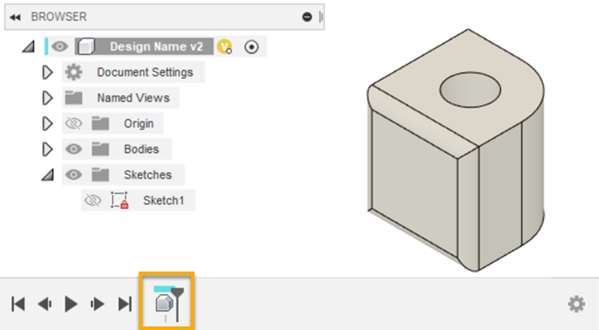 Fusion places earlier direct geometry in one Base Feature and records later work in the Timeline. Source: Autodesk Fusion Help.
The reverse direction is more destructive. Fusion's Direct Modeling Mode help says changing a parametric design to direct mode deletes Timeline features and parametric history. That may be deliberate for a disposable concept or a frozen derivative. It is a poor surprise in the master model five minutes before the drawing goes out.
Autodesk's official “Direct modeling versus parametric modeling” lesson edits the same reciprocating-saw model with both approaches. Source: Autodesk Learning.
Mark the boundary in a hybrid model. Keep the imported or direct Base Feature identifiable, name the later features that carry engineering intent, and avoid burying critical interfaces under anonymous face offsets. A teammate should be able to tell which geometry is authoritative and which edits are local accommodations.
A supplier STEP example#
Imagine a supplier bracket with a mounting face, two locating holes, a cable-relief pocket, and no native history. The new assembly needs the cable pocket 4 mm wider and one locating hole shifted 6 mm.
The pocket is a reasonable direct edit if its surrounding faces are simple and the new width is controlled elsewhere in the release package. Moving the locating hole is riskier. Its position may be related to a mating dowel, an inspection datum, a second part, and a drawing callout. A face move can produce the requested nominal geometry while leaving those relationships implicit.
For that hole, first ask for a corrected native model or a new export. If that is unavailable, make the direct edit, then update the drawing or PMI and verify the mating part. If the same shift must propagate across several configurations, rebuild the interface as parametric features instead of repeating a clever face move twelve times.
This is adjacent to repairing bad topology, but it is not the same job. Use the imported STEP repair workflow when the body has gaps, invalid faces, or translation damage. Use the direct-versus-parametric decision after the geometry is valid and you need to change it.
Validate the result, not the elegance of the tree#
A tidy history can still produce the wrong part. A quick direct edit can be perfectly safe. Validation has to follow the engineering consequence:
- Check body validity and confirm the edit did not create gaps, sliver faces, or self-intersections.
- Measure the changed interface from stable references, not from whatever edge is easiest to click.
- Recheck mates, clearance, interference, mass properties, and motion affected by the change.
- Update drawings, PMI, BOM data, configurations, and manufacturing exports that depend on it.
- Save the native model and the issued neutral file against the same engineering revision.
The CAD version-control guide matters here because a modeling method is not a release process. A direct edit living only in one export is how Friday's quick fix becomes Monday's mystery geometry.
No supplier model, rebuild-time benchmark, or cross-kernel accuracy test was performed for this guide. The mechanisms and product behaviour come from the Autodesk, Onshape, and Shapr3D documentation linked above. The decision framework is an engineering interpretation of those documented capabilities, not evidence that one kernel will solve every face move or that one feature tree will survive every revision.
Use history for the decisions you expect to change together. Use direct editing for geometry that arrived without history and for local changes that do not deserve a rebuild. When you mix them, make the boundary obvious and validate the released result. The best model is not the one that wins an argument about purity. It is the one the next person can change without swearing at your past self.
Related articles
CAD Workflows
Imported STEP file errors: repair, re-export, or rebuild?
Repair an imported STEP file when the fault is local and the intended shape is unambiguous. Request a better export when faults repeat across the model, and rebuild only when missing design intent or widespread bad topology makes repair less trustworthy than remodeling.
CAD Workflows
CAD version control: versions, revisions, and releases
CAD version control should preserve every useful design state while reserving revision labels for approved changes. Release one traceable package of the native model, drawing, BOM, and required exports so manufacturing can identify exactly what was approved.
Tools & News
Adam Migrations: moving CAD feature history between systems
Adam Migrations is an AI-assisted CAD-to-CAD tool that rebuilds parametric history, checks geometry step by step, and transfers model metadata, according to Adam. Its public page names seven CAD systems but leaves exact source-to-destination pairs, versions, and tolerances for a representative-model review.
Newsletter
Get new CAD articles in your inbox
Text-to-CAD guides, new tools, CAD comparisons, and practical tutorials.