

Surface vs solid modeling: choose by the boundary
Surface modeling gives you control over shape and continuity. Solid modeling gives the part volume, mass, and a safer route into drawings, simulation, and manufacturing.
Quick answer
Use surface modeling when the hard problem is controlling an outer shape, repairing faces, or joining complex curvature. Use solid modeling when the part needs volume, mass properties, drawings, simulation, assembly checks, or manufacturing output; most product work uses surfaces to define the skin, then closes or thickens that skin into a validated solid.
The enclosure looks fine until the light catches the join. One patch rolls smoothly into the next, another carries a faint crease, and the cheap mouse has already crossed the same edge six times while the review call goes quiet. The shape is not obviously broken. It just looks like two pieces of plastic being polite to each other.
This is where forcing everything through solid features becomes a pain in the ass. Use surface modeling when the boundary itself is the difficult part: the curve of a grip, the crown of a housing, a repaired face, or a controlled transition between sections. Use solid modeling once the part needs a closed volume, wall thickness, mass properties, ribs, bosses, drawings, simulation, assembly checks, or a manufacturing handoff.
Most useful product models are hybrids. Build and judge the skin as surfaces, turn it into a trustworthy solid, then add the engineering features that make the thing buildable.
A surface body is not a rough solid#
A solid encloses a volume. The CAD kernel can calculate its mass and centre of gravity, cut it with a section, check it for interference, and treat it as material during a boolean operation. A surface body is zero-thickness geometry. It can describe the same outside shape with exact B-Rep faces and edges, but it does not yet say which side contains material.
Autodesk's May 2026 comparison makes the practical split clearly: solid models suit manufacturing, simulation, assemblies, and drawings; surface models suit aesthetic form, complex curvature, and early shape control. Its useful conclusion is that teams normally use both.
| The difficult question | Better starting body | What still has to happen |
|---|---|---|
| Where are the holes, pockets, and machined faces? | Solid | Add manufacturing detail and tolerances |
| How should a grip flow between several uneven sections? | Surface | Close or thicken the skin, then add internal features |
| How do I replace a damaged face on an imported STEP file? | Surface | Trim, patch, stitch, and validate the repaired solid |
| Does this bracket have the required mass and clearance? | Solid | Assign material and verify the assembly context |
| How do I control a styled housing without fighting a dozen fillets? | Surface | Prove continuity, wall thickness, draft, and closure |
Surface versus solid is not the same argument as direct versus parametric modeling. A surface can be parametric. A solid can be edited directly. One choice concerns the kind of boundary you are building; the other concerns whether the change depends on recorded history.
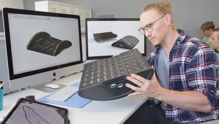 An ergonomic product makes the outside shape a real engineering problem, not decoration around a box. Source: Autodesk Fusion Blog.
Start from the surfaces the product needs#
Take a handheld controller enclosure. The mechanical work includes a PCB, switches, screw bosses, a battery pocket, and a split line. The awkward part is the outside: it must fit a hand, meet a display bezel, clear the triggers, and still release from a mould.
I would not begin by filleting a rectangular solid until it resembles a bar of soap. That approach works for simple cases, then becomes a stack of features that all depend on edges whose names change whenever the outline moves.
A surface-first workflow is more deliberate:
- Define the important sections, silhouette curves, symmetry plane, interface edges, and package envelopes.
- Build the main patches with loft, sweep, boundary, fill, or freeform tools appropriate to the shape.
- Control how the patches meet instead of accepting whatever the default loft produces.
- Trim the skin at real boundaries such as the parting line, bezel opening, or mating flange.
- Mirror, stitch, or knit the patches into a closed shell.
- Convert that shell to a solid or thicken it, then add ribs, bosses, holes, draft, and other production features.
SOLIDWORKS Design Help 2026 describes surfaces as geometry used to create solid features. Its documented uses include thickening a surface, using a surface as an end condition, replacing a face, and creating a solid from surfaces knit into a closed volume. That is the useful relationship. Surfacing is not a separate art department that throws a pretty file over the wall. It is one way of constructing the boundary the solid will inherit.
Autodesk Fusion's official tutorial demonstrates surface creation and editing inside a mechanical CAD workflow. Source: Autodesk Fusion on YouTube.
Continuity decides whether the join disappears#
Two patches can share an edge and still look wrong. The missing idea is surface continuity, which describes how position, direction, and curvature behave across a boundary.
- G0 positional continuity means the patches meet. There is no gap, but there may be a visible corner.
- G1 tangent continuity means their tangent directions agree at the join. The transition has no sharp change in direction.
- G2 curvature continuity means the rate of bending agrees as well. Reflections and highlight lines can flow across the join without an abrupt change in curvature.
Autodesk Fusion Help exposes Connected (G0), Tangent (G1), and Curvature (G2) matching when a T-spline edge is matched to other geometry. Those settings are not quality rankings you apply blindly. A deliberate crease needs G0. A simple mechanical blend may only need G1. A cosmetic housing under glossy light may reveal a G1 join that looked fine in shaded mode.
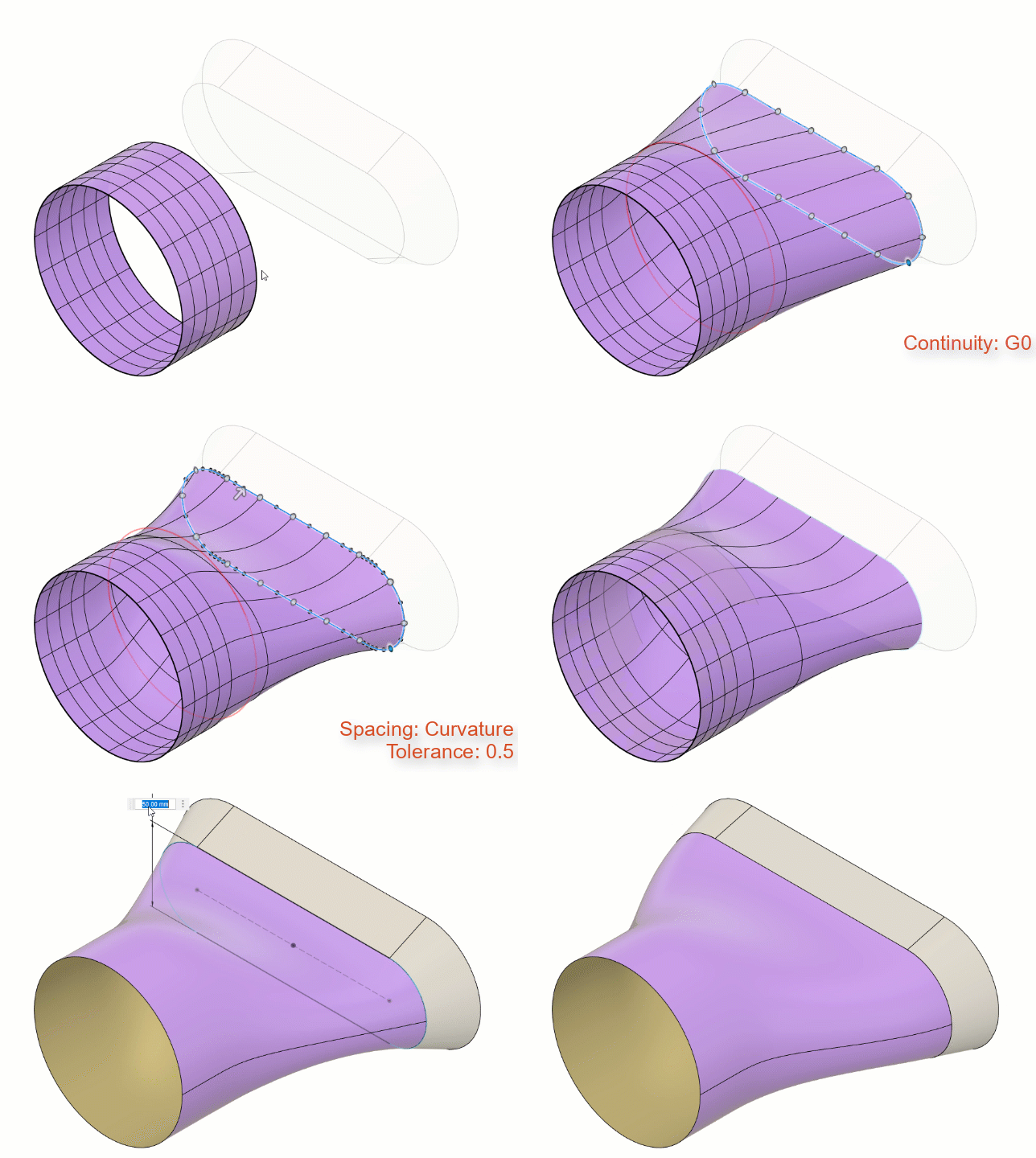 Fusion's Match workflow shows a freeform surface being associated with adjacent geometry. Source: Autodesk Fusion Help.
Autodesk's Fusion analysis-tool guide documents zebra stripes for analysing surface curvature, along with curvature-map and environment-map displays. Use those views, curvature combs, and cross-sections to inspect the join. A shaded viewport can hide a small wobble, especially when the model is grey and the office lights are reflected in the second monitor. Rotate the model and look at the transition rather than admiring the overall silhouette.
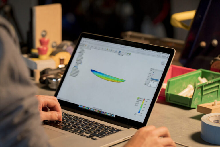 A curvature display makes changes across a styled surface easier to judge than plain shaded geometry. Source: Autodesk's surface-modeling comparison.
Turning the skin into a solid is a release gate#
The conversion button is not proof that the body is ready. First the patches need a coherent boundary.
Trim overlaps at intentional edges. Extend surfaces when two theoretical shapes meet just beyond their original limits. Patch genuine openings. Stitch or knit adjacent faces using a tolerance appropriate to the model and the receiving system. Then ask the kernel to form a solid only after the shell is closed.
This is where imported models become awkward. A tiny gap can leave the result as loose surfaces. A sliver face can make an offset self-intersect. A patch that technically closes a hole may introduce poor curvature or erase the feature that was supposed to mate with another part. The imported STEP repair guide covers the decision between local repair, re-export, and rebuilding when the surface work starts hiding the original intent.
Thickening creates another class of failure. The offset surface may fold through itself at a tight inside radius, collapse around a small feature, or produce a wall that varies in a way the manufacturing process cannot hold. If a 2 mm inward offset cannot fit around a 1 mm concave radius, the software is not being difficult. The requested geometry is fighting itself.
SOLIDWORKS' official long-form session covers practical surfacing operations and failure points. Source: SOLIDWORKS on YouTube.
Put engineering features on the solid#
Once the outer skin closes cleanly, stop treating it like a finished product. A housing still needs wall strategy, screw bosses, snap or fastener access, PCB mounts, connector openings, draft, a parting line, and tolerances at every controlled interface.
Keep stable references between the styled exterior and those functional features. A centre plane, named section, interface sketch, or master layout is safer than hanging a screw boss from whichever trimmed edge happened to exist this morning. The shape will change. The PCB mounting pattern probably should not wander with it.
The hybrid sequence also makes review easier. Industrial design can discuss silhouette and highlights while mechanical engineering checks package space, nominal wall thickness, draft direction, fastening, and service access. The same model can support both conversations without pretending they are the same problem.
This is also the point to distinguish source-reported capability from performed testing. The product behaviours above come from the current Autodesk and SOLIDWORKS documentation and vendor demonstrations. I did not build, thicken, mould, machine, or physically inspect the controller example for this guide, so it contains no measured surface-deviation, wall-thickness, or manufacturing result.
File format can turn a solid back into a skin#
STEP and Parasolid can carry exact surface or solid B-Rep geometry. IGES often appears in surface-heavy handoffs. STL and OBJ carry tessellated mesh instead. Those are different boundaries with different editing consequences.
An exchange file can open looking perfect while the feature tree reports several surface bodies and no solid. That may be acceptable when the recipient wants exterior reference geometry. It is a blocker when they expect volume, mass, boolean cuts, interference checking, or a direct CAM workflow.
Do not call every surface model a mesh. An exact NURBS surface is B-Rep geometry with analytic topology; a mesh approximates the shape with polygons. The B-Rep versus mesh guide explains why that difference survives even when both objects are zero-thickness on screen.
Before handoff, use the CAD file-format guide to choose the representation. Reopen the exported file in a clean session or the receiving CAD system and confirm whether it arrived as the intended solid, surface set, or mesh.
Validate the boundary, then validate the part#
A surface-first model needs two checks. The first asks whether the boundary is coherent. The second asks whether the resulting part works.
For the boundary:
- Find open edges, tiny gaps, duplicate patches, sliver faces, and self-intersections.
- Inspect G0, G1, or G2 continuity where each kind is actually required.
- Use sections and curvature tools to find flat spots, pinches, and unexpected waves.
- Confirm that the stitched shell creates one valid solid with sensible volume and mass properties.
For the part:
- Check minimum wall thickness, local offsets, draft, parting strategy, and tool access.
- Verify interfaces, datums, assembly clearance, and moving envelopes against the surrounding components.
- Rebuild after changing the driving sections so fragile trims and references fail now, not after release.
- Export and reopen the manufacturing representation, then verify body type, units, geometry, and critical measurements.
Surface modeling earns its keep when the boundary is the difficult bit. Solid modeling earns its keep when that boundary must become a part with material, interfaces, and downstream obligations. Use the skin to control the shape. Use the solid to make the shape answerable. The model is ready only when both tell the same story.
Related articles
CAD Workflows
Direct vs parametric modeling: choose for the change
Use direct modeling for local edits to imported geometry, fast concepts, and changes whose intent is obvious from the existing faces. Use parametric modeling when dimensions, relationships, configurations, drawings, and future revisions must update predictably; most production workflows benefit from mixing both deliberately.
CAD Workflows
Imported STEP file errors: repair, re-export, or rebuild?
Repair an imported STEP file when the fault is local and the intended shape is unambiguous. Request a better export when faults repeat across the model, and rebuild only when missing design intent or widespread bad topology makes repair less trustworthy than remodeling.
Text-to-CAD
B-Rep vs mesh in AI generation: why it matters
B-Rep (Boundary Representation) output from text-to-CAD tools contains mathematically exact surfaces, edges, and faces that can be filleted, chamfered, dimensioned, and manufactured. Mesh output (STL/OBJ) is a triangle approximation with no edge or face information, unsuitable for engineering edits or precision manufacturing.
Newsletter
Get new CAD articles in your inbox
Text-to-CAD guides, new tools, CAD comparisons, and practical tutorials.