

CAD assembly interference checks: what a clean result misses
A clean interference report proves less than most release meetings pretend. Check nominal overlap, required clearance, and the full motion path as separate problems.
Quick answer
Run interference detection on the exact released assembly to find overlapping nominal solids, then check minimum clearance and collision through every critical motion. A clean static result does not prove tolerance-safe fit, room for movement, flexible-part behaviour, or manufacturing readiness.
The review call is five minutes old, the coffee has gone cold, and somebody has just rotated the assembly to an angle nobody checked yesterday. A bolt head disappears into a bracket. The model looked tidy in the home view. The drawing was nearly ready. Now the red patch on the screen is explaining why “looks fine” is not an engineering check.
The useful answer is simple: run interference detection on the exact configuration and revision you intend to release, but do not stop there. Static interference finds overlapping nominal geometry at one position. Required clearance, collision through motion, tolerances, deformation, cables, and manufacturing variation are separate checks.
That distinction matters because a green report can be completely honest and still leave you with parts that scrape, seize, or cannot be assembled.
Interference, clearance, and collision answer different questions#
CAD tools use these names with minor variations, but the engineering questions are different:
| Check | The question it answers | What a pass does not prove |
|---|---|---|
| Static interference | Do nominal solid volumes overlap at this position? | Adequate gap, motion, or tolerance-safe fit |
| Clearance | Is the minimum nominal gap at least the value we require? | Collision-free movement or real manufactured variation |
| Collision or dynamic clearance | Do selected parts touch or breach a gap while the mechanism moves? | Loads, deformation, wear, cable behaviour, or every possible pose |
| Tolerance analysis | Will the fit still work across allowed dimensional variation? | Motion under load or manufacturing process capability |
Onshape's Interference Detection help, updated September 24, 2026, describes a direct nominal-geometry test: select parts or bodies and Onshape highlights the interfering mass in red. Autodesk Fusion's Interference tool similarly reports interference between selected solid bodies or components and can include coincident faces.
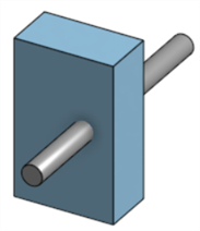 Two nominal parts can look plausible while their volumes overlap. Source: Onshape Help.
Interference volume is useful evidence. It tells you where the geometry overlaps and, in some systems, how much. It does not tell you whether the overlap is an error. A press fit, an O-ring, a modeled thread, and a sheet-metal mistake can all produce red geometry for very different reasons.
Start from the assembly you will actually release#
The first failure mode happens before the analysis button is pressed. The team checks the wrong configuration, a simplified representation, an old supplier part, or an assembly with hidden hardware. The report passes because the risky geometry was never in the calculation.
Start with the released candidate, not the lightweight view that happened to be open:
- Confirm the native assembly, configuration, version, and revision.
- Update external references and imported components.
- Load or resolve the geometry needed by the check.
- Restore suppressed or hidden items that occupy real space.
- Include standard fasteners, purchased parts, and multibody content unless their exclusion is deliberate and recorded.
- Save a named check state so the same scope can be rerun after a change.
This is where performance shortcuts can bite. SOLIDWORKS Design Help 2026 says interference calculations in Large Design Review are approximate, do not report interference volume, and should be recalculated with resolved components for accurate results. The same page allows hidden bodies to be ignored. That can be convenient during diagnosis and disastrous if someone forgets the option before release.
The large-assembly performance guide makes the same broader point: a simplified view is a task-specific working state, not automatically the authoritative geometry for release checks.
Run one broad static sweep before narrowing the scope#
Do the first pass across the full top-level assembly. A hand-picked component pair is useful once you know what you are investigating, but it is a poor discovery method. It only proves that the pairs you remembered to select do not overlap.
Onshape can include standard content and can hide interferences internal to selected subassemblies. SOLIDWORKS can treat subassemblies as single components, include multibody and surface-body interferences, and separate common fastener or matching cosmetic-thread results. Each option changes the meaning of the list, so put the settings beside the result rather than treating the screenshot as self-explanatory.
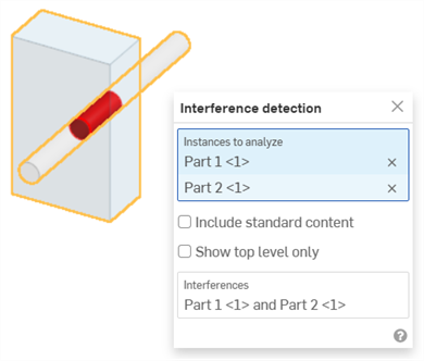 Onshape lists the parts involved and colours the interfering mass red. Source: Onshape Help.
Onshape's official walkthrough shows selection, calculation, and result inspection. Source: Onshape on YouTube.
Sort the result by consequence, not just volume. A tiny interference at a cosmetic thread may be expected. A smaller overlap at a bearing shoulder, connector latch, sealing face, or moving linkage may stop the product from assembling. Large red blobs are visually satisfying because they are easy to fix. The irritating little ones are often the expensive ones.
Triage intentional overlaps without teaching the tool to lie#
Every result needs an engineering disposition:
- Error: geometry must change.
- Intentional fit: supported by a fit, preload, seal, or manufacturing requirement.
- Representation artifact: cosmetic threads, simplified hardware, or faceted display geometry.
- Scope problem: stale, missing, duplicated, or wrongly configured content.
- Needs another analysis: clearance, tolerance, motion, deformation, or process review.
Do not globally ignore a class of results because one example is harmless. SOLIDWORKS 2026 can retain ignored interferences and place matching cosmetic threads in their own folder. That is better than deleting evidence, provided the saved result explains why each exception is acceptable.
The same documentation warns that curved geometry which is coincident or extremely close can create false positives when facets collide. That is a reason to inspect the underlying faces, not a reason to wave away every small result. A false positive and a tiny real clash look equally small in a meeting thumbnail.
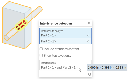 The bounding box helps locate a small overlap inside a busy model. Source: Onshape Help.
Check the gap, not only the absence of overlap#
Two parts separated by 0.01 mm do not interfere in a nominal model. They may still be impossible to manufacture, assemble, coat, lubricate, or move without contact.
SOLIDWORKS Clearance Verification checks the minimum distance between selected components and reports gaps below a specified acceptable value. The threshold should come from function: tool access, paint or plating, thermal growth, bearing movement, wire bend radius, a hand gap, or whatever the design actually needs.
A nominal clearance is not a tolerance stack. If a shaft is modeled at 20.000 mm and its bore at 20.010 mm, CAD sees 0.010 mm of diametral difference. Manufacturing sees two tolerance zones, surface finish, temperature, and a supplier who may use a different measuring method on Friday afternoon. The model can locate the narrow gap. It cannot decide whether that gap is a reliable fit.
Use a clearance check to find where to do the harder work, then evaluate dimensions and tolerances at those interfaces. For a critical fit, connect the result to the drawing or PMI, the inspection method, and the release record.
Static checks do not cover the path between positions#
A hinge can be clean when closed and clean when open while clipping the enclosure halfway through. Checking endpoints is like checking the first and last frame of a video and declaring the plot coherent.
For motion, define the actual mates or joints and inspect the full travel. SOLIDWORKS Collision Detection can stop a dragged component when it touches another component. Its Dynamic Clearance mode reports the changing minimum distance and can stop motion at a specified gap. Autodesk also documents using Fusion's Interference command through joint motion, but the check is only as complete as the positions you evaluate.
Autodesk's official “Interference detection and contact sets” lesson demonstrates interference results and contact behaviour in Fusion. Source: Autodesk Learning.
Test the poses the product can reach, including the ugly ones:
- travel limits and hard stops
- maintenance and assembly positions
- doors, covers, latches, and cable-service loops
- mated components that move because another component is dragged
- alternative configurations and optional hardware
- tool, hand, fixture, and fastener access where relevant
Flexible hoses, wires, belts, fabric, seals, and loaded springs often need a conservative envelope or a separate simulation. A centreline is not a hose. A perfectly straight cable in CAD is usually the first clue that nobody has checked the real one.
Imported and simplified geometry need extra suspicion#
An imported STEP body may contain repaired faces, sliver surfaces, or topology that changed during translation. A mesh may only approximate the intended surface. A simplified supplier model may remove small features that create the real collision.
Run the geometry checks in the imported STEP repair workflow before trusting the assembly result. If the supplier provides an envelope or keep-out model, record whether it represents nominal geometry, maximum material, a motion envelope, or merely a lightweight visual. Those are not interchangeable.
The same caution applies to model substitution. A simplified motor cylinder may be safe for layout but useless for checking connector access. A defeatured gearbox may preserve its mounting face while deleting the oil plug that collides with the frame. Simplification should remove irrelevant detail, not the evidence the next check needs.
Make the check part of release evidence#
The most useful interference report is repeatable. Record the assembly revision, configuration, analysis scope, options, required clearance, ignored-result dispositions, and date. Then rerun it after any change to geometry, mates, purchased components, or configuration logic.
Link the evidence to the same engineering revision as the model, drawing, BOM, and manufacturing exports. If the report belongs to yesterday's assembly, it is not release evidence. It is a historical curiosity with a nice green icon.
No proprietary assembly, tolerance study, physical prototype, or independent solver benchmark was tested for this guide. The workflow is based on the current vendor documentation linked above. The limits are therefore deliberate: vendor tools can calculate nominal geometry accurately within their stated modes, but only the engineering team can define the required gap, acceptable intentional overlap, motion scope, and manufacturing consequence.
The right release question is not “Did the interference tool pass?” It is “Which geometric failure modes did we check, on which revision, and what still sits outside the model?” That question is less comfortable. It is also much cheaper than discovering the answer beside a half-built machine.
Related articles
CAD Workflows
Large CAD assemblies: make them faster without losing trust
Speed up a large CAD assembly by measuring which work is slow, reducing unnecessary mate solving and feature regeneration, and using task-specific lightweight or simplified representations. Keep the full released model authoritative, and restore it for interference, mass, drawing, export, and manufacturing checks.
CAD Workflows
CAD version control: versions, revisions, and releases
CAD version control should preserve every useful design state while reserving revision labels for approved changes. Release one traceable package of the native model, drawing, BOM, and required exports so manufacturing can identify exactly what was approved.
CAD Workflows
Imported STEP file errors: repair, re-export, or rebuild?
Repair an imported STEP file when the fault is local and the intended shape is unambiguous. Request a better export when faults repeat across the model, and rebuild only when missing design intent or widespread bad topology makes repair less trustworthy than remodeling.
Newsletter
Get new CAD articles in your inbox
Text-to-CAD guides, new tools, CAD comparisons, and practical tutorials.