

CAD fillet failures: diagnose the edge before changing the radius
A failed fillet is usually a local geometry problem wearing a useless error message. Isolate the first bad edge, inspect the available space and corner, then choose the smallest honest repair instead of dragging the radius until the preview turns green.
Quick answer
To fix a failed CAD fillet, suppress later features, remove tangent-chain selection, and test one edge at a time to locate the first failure. Inspect short edges, narrow faces, endpoints, and multi-edge corners; then use a smaller, partial, or variable fillet, change the corner treatment, or build a face blend only when that matches the design intent.
The model is due out in ten minutes. One last 6 mm edge round should make the housing less likely to remove skin from the person carrying it. Instead, the preview vanishes, the feature tree turns red, and the warning dialog offers the geometric wisdom of a smoke alarm.
Changing the radius to 5.9 mm makes it work. Nobody in the review call knows why. The half-cold coffee beside the cheap mouse is no help either.
To fix a failed CAD fillet, first suppress later features, turn off automatic tangent-chain selection, and test one edge at a time. That isolates the first location the kernel cannot solve. Inspect the local face width, short edges, endpoints, and any corner where several rounds collide. A smaller radius is a diagnostic test, not automatically the right design. The honest repair may be a partial or variable fillet, a different corner treatment, a reordered feature, repaired source geometry, or a face blend.
This is a source-based diagnostic workflow using current Autodesk Fusion and Onshape documentation. I did not run a cross-kernel benchmark or test a proprietary model set. The screenshots and videos are first-party demonstrations, not evidence that every CAD kernel will resolve the same edge in the same way.
What the fillet is trying to build#
A solid-model fillet is not paint on an edge. The operation trims the adjacent faces and inserts a transition surface between them. Autodesk's Fusion reference describes an exterior round as removing material and an interior fillet as adding it. The result still has to form valid B-Rep geometry with coherent faces, edges, and vertices.
That is why the error often appears far from the number in the radius box. A constant radius may fit through most of the edge, then collide with a nearby wall at one end. Two acceptable rounds may become impossible where they meet a third edge. A tiny sliver face may leave the operation with no clean place to trim. The visible edge is only the path; the surrounding faces decide whether a transition can exist.
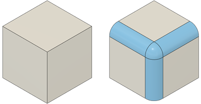
Fusion treats the multi-edge corner as a separate construction choice, shown here with Rolling Ball. Source: Autodesk Fusion Help.
When a fillet fails, read the message, but inspect the geometry. A generic rebuild warning cannot tell you whether the engineering radius is wrong, the local topology is damaged, or the selected corner simply needs another construction.
Find the first edge that actually fails#
A selection of twenty edges produces one red feature and almost no useful evidence. Reduce the problem until it becomes specific.
- Save a version or branch before changing the feature tree.
- Suppress features after the failed fillet so downstream errors do not cover the first failure.
- Turn off tangent propagation or tangent-chain selection.
- Remove every selected edge, then add one edge and rebuild.
- Add the next edge only after the previous result succeeds.
- When a chain fails, divide it into smaller groups until one edge or one corner reproduces the problem.
This is the CAD equivalent of unplugging one cursed appliance at a time instead of replacing the fuse box. If a single straight edge fails, inspect its local faces and endpoints. If each edge works alone but the group fails, investigate the intersection and corner order. If the feature succeeds until a later edit, the real fault may be a changed reference or a downstream dependency.
Onshape's official Tech Tip demonstrates choosing and applying fillets in the model rather than treating every edge round as the same operation. Source: Onshape on YouTube.
Do not delete a failing feature and recreate it blindly. First record which edge, radius, and upstream revision failed. Otherwise the new feature may work only because the selection changed, leaving the actual dependency problem ready for the next revision.
Test the local space without surrendering the requirement#
Lowering the radius is useful because it asks a clean question: is local space the limit? Try a deliberately small value. If that fails too, stop dragging the number downward. Look for damaged faces, zero-thickness conditions, an unsuitable selection, or a corner that needs a different method.
If the small radius works, increase it until the preview approaches the failure. Then inspect the tightest region with sections and measurements:
- a face narrower than the requested transition;
- a short edge that disappears before the fillet reaches its endpoint;
- a nearby hole, pocket, rib, shell, or draft face that the blend runs into;
- changing curvature that leaves less room near one end than the shaded view suggests;
- another fillet or chamfer consuming the face needed by this one;
- a three-edge corner where separate fillets must be resolved together.
The largest radius that happens to rebuild is not a manufacturing or structural requirement. It is merely the current geometric ceiling, and even that ceiling can move when an upstream dimension changes. Keep the intended radius tied to ergonomics, stress, molding, casting, machining, or product styling. Change it only when the engineering reason changes.
Stop asking one radius to survive every section#
A constant-radius fillet is simple until the available space is not constant. Onshape's fillet documentation, updated 9 October 2026, supports partial fillets, variable values at vertices or points, asymmetric measurements, and circular, conic, or curvature-controlled cross sections. Fusion similarly documents constant, chord-length, variable, and asymmetric radius types.
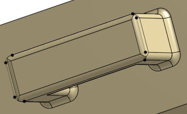
A variable fillet lets the transition fit changing local space without shrinking the entire edge to the smallest value. Source: Onshape Help.
Use a partial fillet when only part of the edge needs rounding and a deliberate stop position can be dimensioned. Use a variable fillet when the radius genuinely needs to change along the edge. Use an asymmetric fillet when the transition must consume different amounts of the two adjoining faces.
Those controls are not error-message suppressors. A variable fillet with six arbitrary points may rebuild today and become impossible to review tomorrow. Use the fewest controls that express a real requirement, then inspect the resulting transition instead of trusting the green checkmark.
Treat a multi-edge corner as its own problem#
Three or more filleted edges meeting at a vertex force the CAD system to close a corner, not merely round independent edges. Fusion exposes Rolling Ball and Setback corner types. Rolling Ball combines the rounded edges at the corner; Setback blends the rounded corners into the adjacent faces.
When individual edges succeed but their shared corner fails, try these in order:
- Fillet the dominant edge first and rebuild.
- Add secondary edges as a separate feature.
- Reverse that order and compare the resulting faces, not only whether both trees stay green.
- Test the available corner types.
- Split a large functional radius from small cosmetic rounds.
Feature order changes geometry. A 10 mm structural fillet followed by a 1 mm edge break does not necessarily produce the same faces as the small round first. Choose the order that preserves the important parent faces and design intent. The shortest tree is not automatically the most stable one.
Decide whether edge overflow may change the boundary#
An edge can constrain a fillet into an awkward local shape. Onshape's Allow edge overflow option lets the fillet modify or remove tangent edges on its new face to form a smoother continuous surface. The same documentation lets you name edges that must be kept.
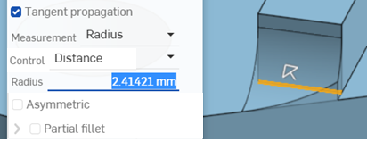
Allow edge overflow gives the generated fillet permission to change tangent-edge boundaries. Source: Onshape Help.
That can rescue a transition, but it is a topology decision. Check whether a hole rim, split face, downstream selection, drawing edge, or manufacturing boundary moved or disappeared. If a later sketch was projected from the deleted edge, the successful fillet may merely move the red warning farther down the tree.
This is why stable references matter. The fully constrained sketch workflow recommends locating functional geometry from origins, datums, and interfaces rather than decorative or generated edges. A fillet edge is especially fragile because its existence depends on neighbouring faces and feature order.
Use a face blend when the edge is the wrong abstraction#
An edge fillet begins with an existing edge or chain. A face blend starts from two face sets and constructs a transition between them. Onshape's Face Blend help, also updated 9 October 2026, supports connected or disconnected faces, rolling-ball or swept-profile cross sections, side continuity, hold lines, cliff edges, caps, and plane or face limits.

A rolling-ball face blend is driven by the selected face sets rather than one pre-existing model edge. Source: Onshape Help.
Onshape's official comparison shows where a face-driven transition differs from an edge fillet. Source: Onshape on YouTube.
Choose a face blend when the intended transition belongs between surfaces and the current edge is unstable, fragmented, or absent. Do not choose it because the dialog has more controls and looks impressive. A detached or capped blend may create new surface geometry that still needs trimming, joining, continuity inspection, and conversion back into a trustworthy solid.
This is also where the surface-versus-solid modeling guide becomes relevant. If the product's outer skin drives the shape, build and inspect that skin deliberately. Do not keep stacking edge rounds onto a block until it resembles the styling model by accident.
Repair imported geometry before decorating it#
Imported STEP geometry can contain repaired faces, split edges, narrow slivers, and topology that differs from the source system. A fillet may expose those problems because it asks adjacent faces to extend, trim, and meet again.
Run the imported STEP repair workflow first. Confirm the body is solid, inspect the suspect region, and decide whether to heal locally, request a cleaner export, or rebuild the feature. Deleting old rounds from an imported model and applying new ones can be sensible direct modeling. Adding fresh fillets on top of broken or tiny translated faces is usually geometry archaeology with worse lighting.
Keep exchange tolerance in perspective. A different export can change how faces are split or approximated, but it cannot make an impossible radius fit into a narrow region. Repair evidence and design evidence are separate.
Validate more than the successful preview#
A fillet that rebuilds can still be a poor transition. After the repair:
- section the tight regions and inspect for sliver faces or abrupt thickness changes;
- use zebra stripes or a curvature display where reflection quality and surface continuity matter;
- measure the effective radius or width at the locations the drawing controls;
- rerun draft, wall-thickness, interference, mesh, or manufacturing checks affected by the changed faces;
- rebuild every configuration and assembly context that uses the part;
- export the actual release format, reopen it, and check the body and critical interfaces;
- confirm drawings, dimensions, annotations, CAM references, and downstream selections still point at the intended geometry.
No fillet command proves fatigue life, moldability, castability, machinability, or safe handling. It only creates geometry. The engineering team still owns the reason for the radius and the evidence that the finished transition works in the real process.
The reliable sequence is boring: isolate one edge, inspect the local space, test the corner, choose the right construction, and validate the downstream model. That is slower than spinning the radius wheel until the preview appears. It is much faster than explaining to a machinist why a Friday export contains a blend nobody can reproduce.
Related articles
CAD Basics
Surface vs solid modeling: choose by the boundary
Use surface modeling when the hard problem is controlling an outer shape, repairing faces, or joining complex curvature. Use solid modeling when the part needs volume, mass properties, drawings, simulation, assembly checks, or manufacturing output; most product work uses surfaces to define the skin, then closes or thickens that skin into a validated solid.
CAD Workflows
Imported STEP file errors: repair, re-export, or rebuild?
Repair an imported STEP file when the fault is local and the intended shape is unambiguous. Request a better export when faults repeat across the model, and rebuild only when missing design intent or widespread bad topology makes repair less trustworthy than remodeling.
CAD Workflows
How to fully constrain a CAD sketch without making it brittle
Fully constrain a CAD sketch by anchoring its position to a stable origin or reference, applying geometric constraints that express design intent, and adding only the dimensions needed to control size and location. Drag-test the sketch, diagnose remaining degrees of freedom, and avoid using Fix or redundant dimensions merely to make the status indicator turn fully constrained.
Newsletter
Get new CAD articles in your inbox
Text-to-CAD guides, new tools, CAD comparisons, and practical tutorials.