

Injection molding DFM: check the CAD before tooling
A clean plastic part can still trap itself in the tool, sink around a boss, or demand an expensive side action. Define the mold direction first, then check draft, undercuts, wall thickness, and knife edges before the quote becomes steel.
Quick answer
Before releasing an injection-molded part, define its pull direction and parting line, apply material- and finish-specific rules, then inspect draft, undercuts, wall thickness, and knife edges. Resolve the geometry alerts, review gates, cooling, shrinkage, and ejection with the molder, and repeat the checks on the exact revision sent for tooling.
The enclosure looks finished on the second monitor. The bosses line up, the lid closes, and the half-cold coffee beside the mouse has survived another review call. Then the molder rotates the part, points at one innocent-looking clip, and explains that the core cannot leave the plastic without passing through it.
That is the moment a neat CAD model becomes a tooling problem.
Before releasing an injection-molded part, choose the mold pull direction and likely parting line, then check draft, undercuts, wall thickness, and knife edges against rules agreed with the molder. Fix the major geometry in that order, rerun the analysis on the exact release candidate, and treat the result as a DFM screen rather than proof that the mold will fill, cool, eject, and hold tolerance.
The workflow below is based on current Autodesk, Onshape, and Protolabs documentation. I did not run a mold-flow study, cut tooling, mold samples, or inspect production parts for this article. The screenshots and videos are vendor documentation, not independent test results.
Start with the mold, not the colour plot#
Autodesk's 5 August 2026 DFM guide makes the broad point: manufacturing constraints belong in the design work, not in a late inspection ritual. For injection molding, that means the CAD check needs inputs from the intended process before any red or green face can mean much.
Write down these decisions first:
- The resin family, expected shrink behaviour, nominal wall range, and any filled or reinforced grade that changes the rules.
- The cosmetic finish and texture, because a textured wall normally needs more release angle than a polished one.
- The primary opening direction of the tool and which side is likely to carry the core and cavity.
- The likely parting line, shutoffs, ejector side, gate region, and surfaces where witness marks are unacceptable.
- The critical interfaces and dimensions that must survive any DFM-driven geometry change.
Do not pick the pull direction because it makes the first analysis mostly green. Pick it from how the part can be tooled, filled, cooled, opened, and ejected. A direction that clears the outside walls may trap an internal hook. A lovely hidden parting line may create a shutoff that is miserable to machine or maintain.
Fusion's Design Advice documentation says the analysis inherits thickness and draft values from the plastic rule assigned to the component. If no rule is assigned, Fusion can use the design's default. That default is a starting condition, not silent approval from the eventual supplier.
Run the broad DFM screen once#
In Fusion, Design Advice asks for a solid body and pull direction, then reports four alert families: thickness, undercuts, draft, and knife edges. The documented workflow lets you isolate each alert, inspect the highlighted geometry, apply modeling changes, and analyze the body again.
Autodesk's official Design Advice lesson walks through thickness, undercut, draft, and knife-edge results. Source: Fusion Help.
Run this broad pass before polishing ribs, labels, snaps, and cosmetic breaks. It tells you whether the basic shell and opening direction are plausible. Save the analysis with the model where the CAD system supports that, and record the rule used. A screenshot with red patches but no pull direction, material rule, or revision is evidence without a legend.
Use the result as a triage list:
| Alert | What it usually means | First question to ask |
|---|---|---|
| Draft | A face is too close to parallel with the pull direction | Is the pull direction correct, and what draft does the material and finish need? |
| Undercut | Straight-line ejection is obstructed | Can the feature move, reverse, become a shutoff, or justify a side action? |
| Thickness | The wall is outside the rule or varies too much | Is the region structural, cosmetic, or merely unnecessary mass? |
| Knife edge | A gap or tip falls below the chosen threshold | Can the edge gain thickness or be replaced by a radius or shutoff? |
Do not fix the easiest alert first. Pull direction and parting strategy sit upstream of almost everything else. Change either one late and yesterday's correct draft may point the wrong way.
Read draft relative to one declared direction#
A draft angle is measured relative to the direction in which the tool opens and the part releases. Without that direction, “two degrees of draft” is just an angle floating in space.
Fusion's Draft Analysis applies a continuous gradient to a selected body. It can show subtle angle changes, zero-draft regions, likely undercuts, and possible parting-line positions. Onshape's Draft feature documentation, updated 9 October 2026, distinguishes neutral-plane draft from parting-line draft. Those are different modeling decisions: one holds a plane fixed while faces rotate; the other lets draft reverse across a chosen split.
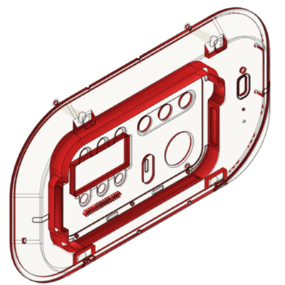
The Draft result highlights faces that fall outside the plastic rule's minimum angle. Source: Autodesk Fusion Help.
Autodesk's official “Analyze draft on a design” lesson demonstrates Draft Analysis, Accessibility Analysis, and Minimum Radius Analysis. Source: Autodesk Learning.
Protolabs gives 1 to 2 degrees as a common starting point, with more for textured surfaces. Treat that as supplier guidance, not a law of plastics. Depth, resin, texture, steel condition, ejection method, tolerance, and the molder's tooling practice can all change the requirement.
Inspect every wall, rib, boss, clip, pocket, embossed character, and recessed control surface. A large outside wall is obvious. The tiny return face under a snap is the one that waits until the tooling quote to become expensive.
Separate an undercut from insufficient draft#
Insufficient draft makes a face reluctant to release. An undercut prevents straight withdrawal along the selected pull direction. Increasing draft does not rescue a hook whose geometry sits behind the mold steel.
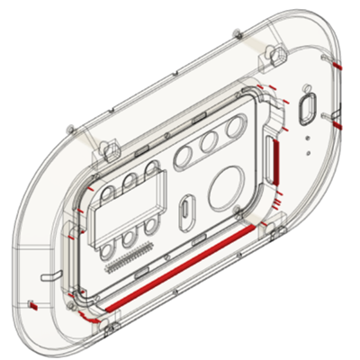
Fusion identifies regions that obstruct ejection along the selected direction. Source: Autodesk Fusion Help.
For every undercut, choose a disposition rather than merely clearing the red overlay:
- Remove or relocate the feature when it adds little function.
- Reorient the feature so it releases with the main pull.
- Turn the geometry into a shutoff when the toolmaker confirms the contact, angle, and steel condition are workable.
- Use a snap-through, bumpoff, collapsible core, lifter, pickout, or side action only when material behaviour, geometry, volume, maintenance, and cost justify it.
- Split the part when one molded body is forcing the tool to perform gymnastics for no useful product reason.
Side actions are not forbidden. They are a cost and reliability decision. The poor habit is discovering one after the tool layout has already been priced around a simple two-plate assumption.
The parting line belongs in the same review. Moving it can remove one undercut and create another. It can shift flash or mismatch onto a sealing face, a cosmetic surface, or a dimension that matters in assembly. Show the proposed line in the review rather than leaving the supplier to infer it from a neutral STEP file.
Check wall thickness as a cooling problem#
The wall-thickness map is not a request to make every face numerically identical. It is a way to find abrupt changes, thick masses, thin flow restrictions, and local regions that will cool or fill differently from the surrounding shell.
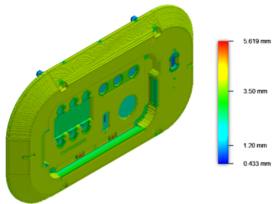
The full-range view maps thick and thin regions instead of showing only out-of-rule alerts. Source: Autodesk Fusion Help.
Protolabs links thick sections with sink, voids, and warping, and recommends coring unnecessary mass. Its guide also treats rib and boss dimensions as ratios to the adjoining wall rather than isolated numbers. That is the right mental model. A 3 mm boss wall is not good or bad by itself; its relationship to the nominal shell and the chosen resin decides whether it becomes a cooling problem.
For a small electronics enclosure, work from the main shell outward:
- Set the nominal wall from material, flow length, stiffness, cosmetic, safety, and supplier requirements.
- Shell the main form or otherwise establish a controlled offset.
- Core bosses rather than leaving solid cylinders attached to a thin wall.
- Use ribs to move stiffness away from thick mass, then check their thickness and base transitions against the molder's rule.
- Blend genuine thickness changes gradually where the product allows it.
- Recheck the cosmetic face opposite every boss, rib junction, and thick corner.
The Fusion gradient is particularly useful around freeform shells. An offset can thicken or collapse locally where curvature becomes tight. That failure can look smooth in shaded mode, much like a cheap drawer that closes nicely until the runner reaches one bent section.
Knife edges are geometry warnings, not trivia#
A knife edge appears where two surfaces meet in a very thin wedge or a gap falls below the chosen rule. In tooling, that can mean fragile steel, poor fill, flash-prone shutoffs, or an edge that will not remain sharp after real material and process variation arrive.
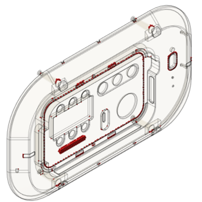
The knife-edge check isolates gaps and tips below the configured threshold. Source: Autodesk Fusion Help.
Inspect thin lips, deep logo strokes, snap roots, vent slots, shutoffs, and the ends of tapered ribs. Add a small radius, widen the edge, move the split, or remove decorative detail where it asks the tool to carry a fragile sliver of steel.
Do not confuse a knife-edge warning with a universal minimum dimension. The correct threshold depends on the tool material, machining method, resin, flow, finish, and maintenance expectation. Set it with the supplier, then keep that setting with the analysis record.
Fix in an order that does not undo itself#
Injection-molding edits are tightly coupled. Adding draft changes the outside dimension at one end of a wall. Coring a boss changes local thickness. Moving a parting line changes which way several faces must release. A sensible sequence reduces the number of times you rebuild the same geometry:
- Confirm material, finish, tooling assumptions, pull direction, and parting strategy.
- Establish a coherent main shell and nominal wall.
- Remove major undercuts or document the required mold actions.
- Apply draft to the main walls, then ribs, bosses, snaps, and small details.
- Correct thick regions, thin restrictions, and knife edges without reintroducing trapped geometry.
- Add final radii and cosmetic details after the moldable structure is stable.
- Rerun the full check, then inspect the changed assembly interfaces and tolerance stack.
Feature order matters. Drafting the outside shell before adding bosses and ribs is easier to reason about than selecting forty-seven scattered faces at the end. For complex styling, the surface-versus-solid workflow helps establish the outer skin, but the closed solid still needs wall, draft, and release checks.
A green DFM screen is not a mold-flow result#
Design Advice checks geometry against declared rules. It does not prove where the gate belongs, how the cavity fills, where weld lines or air traps appear, how pressure changes through the flow path, how cooling distorts the part, or how fibre orientation affects shrinkage.
It also does not prove that ejector pins can push the part without marking or bending it, that a shutoff will survive production, that the mold can be machined and serviced economically, or that the chosen tolerance is capable in the specified resin. Those questions need the tool designer, molder, material data, and, where the risk warrants it, molding simulation and physical samples.
The earlier AI CAD for injection molding article explains why a generated plastic-looking shape is not a manufacturing-ready part. This workflow answers the next question: once you have a real solid, how do you expose the obvious tooling conflicts before asking somebody else to find them?
Release the analysis with the model#
A neutral STEP file can carry the drafted final geometry, but it will not normally carry the native plastic rule, the saved colour map, the reason an undercut was accepted, or the mold direction you used. The CAD file-format guide explains why geometric exchange and design intent are different things.
Put the manufacturing assumptions beside the release:
- native model and neutral export revision;
- resin and finish assumption;
- nominal wall and analysis-rule values;
- pull direction and proposed parting line;
- unresolved undercuts and their planned tool actions;
- accepted alerts with engineering reasons;
- DFM report, screenshots, or saved analysis state;
- supplier review outcome and any simulation or sample evidence still required.
Then reopen the exact export, confirm body count, units, wall geometry, and critical interfaces, and tie it to the same engineering revision as the drawing and tolerance stack. A green analysis on yesterday's file is no more useful than a perfect drawing of the wrong revision.
The best result is not a model with no coloured warnings. It is a part whose pull direction, split, draft, wall strategy, exceptions, and remaining manufacturing risks can be explained before anyone cuts steel. That is when the CAD stops being a nice plastic shape and starts becoming a defensible tooling input.
Related articles
Text-to-CAD
AI CAD for injection molding: draft angles, wall thickness, and reality
AI-generated CAD models are unsuitable for injection molding without extensive rework. Current text-to-CAD tools don't apply draft angles, don't maintain uniform wall thickness, ignore gate and parting line considerations, and don't account for shrinkage. Molding requires DFM expertise that AI doesn't yet have.
CAD Basics
Surface vs solid modeling: choose by the boundary
Use surface modeling when the hard problem is controlling an outer shape, repairing faces, or joining complex curvature. Use solid modeling when the part needs volume, mass properties, drawings, simulation, assembly checks, or manufacturing output; most product work uses surfaces to define the skin, then closes or thickens that skin into a validated solid.
CAD Workflows
How to calculate a CAD tolerance stack-up
Calculate a CAD tolerance stack-up by defining the functional output, drawing a signed dimension loop through the features that control it, and combining each contributor first by worst case. Use RSS or Monte Carlo analysis only when process distributions, independence, and assembly behaviour are supported by data, then verify the result against physical inspection and the released datum scheme.
Newsletter
Get new CAD articles in your inbox
Text-to-CAD guides, new tools, CAD comparisons, and practical tutorials.