

How to fully constrain a CAD sketch without making it brittle
A sketch should stop moving for reasons another designer can understand. Anchor it to stable references, encode functional relationships, and debug the remaining freedom before adding another desperate dimension.
Quick answer
Fully constrain a CAD sketch by anchoring its position to a stable origin or reference, applying geometric constraints that express design intent, and adding only the dimensions needed to control size and location. Drag-test the sketch, diagnose remaining degrees of freedom, and avoid using Fix or redundant dimensions merely to make the status indicator turn fully constrained.
One corner of the plate moves on the review call, and the neat hole pattern goes with it. The sketch looked finished five minutes earlier. Now the blue line under the cheap mouse is sliding around like a drawer with one rail missing, while the dimension you thought controlled it sits there looking innocent.
A reliable sketch does not merely stop moving. It stops moving for reasons the next person can understand. Anchor the sketch to a stable origin or interface, use each sketch constraint to express a real relationship, and add dimensions only for values the design actually needs to control. Then drag-test the geometry and account for every remaining degree of freedom before calling it done.
Do not scatter Fix constraints across the sketch until the colour changes. That can produce a fully constrained sketch whose intent is buried under coordinates nobody meant to own. Fully constrained is a solver state. Predictable revision is the engineering result.
This is a source-based workflow using documented Onshape and Autodesk Fusion behaviour. I did not benchmark sketch solvers or test the same model across CAD kernels for this guide.
Fully constrained means zero unintended movement#
A planar sketch begins with geometry that can translate, rotate, change length, or change shape. A geometric constraint solver finds positions that satisfy all declared relationships and dimensions together. Each useful rule removes or couples some freedom until the intended geometry has no motion left.
Onshape's constraint help, updated 9 October 2026, makes the state visible: blue sketch entities are underconstrained, black entities are fully constrained, and red entities indicate a constraint problem. Autodesk Fusion uses its own interface language, but the underlying test is the same. If geometry can still move in a way the design does not intend, the sketch is not fully controlled.
The words need one qualification. A sketch may contain construction geometry that is deliberately left free during concept work. A derived or projected entity may be controlled by external geometry rather than local dimensions. The useful release rule is not "everything must be black at any cost." It is "every freedom that can change the part must be intentional, visible, and reviewable."
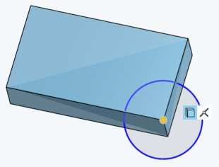
Onshape uses a blue-backed constraint to distinguish geometry referenced from another sketch. External references can control a sketch while also making its dependency less local. Source: Onshape Help.
Separate shape, size, and position#
Constraint problems become easier when you stop asking one dimension to do three jobs.
- Geometric constraints control relationships such as coincident, concentric, horizontal, vertical, parallel, perpendicular, tangent, equal, midpoint, and symmetry.
- Dimensional constraints control values such as length, diameter, radius, angle, and distance.
- Reference geometry controls where the sketch sits relative to the part, assembly, or coordinate system.
Onshape's current list also includes Fix, Use, Intersection, Pierce, and curvature continuity. Those tools are useful, but they carry different kinds of intent. A perpendicular constraint says two lines must remain at 90 degrees. A 90-degree dimension can say the same thing numerically. Applying both may be redundant. A Fix constraint says the selected geometry must remain where it is now, without explaining which feature or datum makes that location correct.
I prefer to establish the shape with relationships first, then size it, then locate it. A centred rectangle, for example, is easier to revise when symmetry or midpoint relationships keep it centred and two dimensions control width and height. Four independent corner coordinates may produce the same shape today, but they turn a simple width change into a small accounting exercise.
Autodesk Fusion demonstrates its twelve sketch-constraint types and how each relationship changes geometry. Source: Autodesk Fusion on YouTube.
Start with the reference that survives revision#
The first useful constraint is often positional. A beautifully dimensioned profile can still slide or rotate if nothing ties it to a stable reference.
Choose the reference from the function of the part:
- Use the sketch origin or a principal plane when the part is naturally symmetric around the coordinate system.
- Use a mounting face, shaft axis, hole centre, or interface plane when another component defines the location.
- Use construction lines and centre points to carry symmetry, pitch, and alignment without turning every edge into a driving reference.
- Use projected geometry only when the upstream dependency is deliberate and likely to survive the expected revision.
Avoid locating new geometry from a fillet edge, trimmed corner, or decorative outline merely because it is easy to click. Those edges are topology, not necessarily design intent. A later feature edit can rename or remove them, leaving the sketch attached to yesterday's accident.
This is the same decision discussed in the direct-versus-parametric modeling guide. Parametric history earns its keep only when the recorded dependency represents the change you expect next.
Work through one mounting plate deliberately#
Consider a 100 mm by 60 mm mounting plate with four equal holes on an 80 mm by 40 mm pattern and a horizontal slot centred between them. The finished sketch has several kinds of intent:
| Intent | Constraint or dimension | Why it belongs |
|---|---|---|
| Plate stays centred | Rectangle centre coincident with the origin, or symmetric about two centre lines | Width and height can change without shifting the interface |
| Plate remains rectangular | Horizontal, vertical, perpendicular, or a rectangle tool's inferred relations | The corners do not need four independent angle dimensions |
| Holes remain equal | Equal-diameter constraint plus one diameter | One controlled hole size drives the pattern |
| Pattern stays centred | Symmetry about horizontal and vertical construction lines | Pitch changes do not move the pattern off the plate centre |
| Pattern spacing is controlled | One horizontal pitch and one vertical pitch dimension | These are functional interface values |
| Slot stays centred | Midpoint or symmetry constraint to the origin | Slot length can change without walking sideways |
Start with the origin and construction axes. Constrain the rectangle's shape, then add width and height. Add one hole, dimension its diameter and position, then create the symmetric set or a sketch pattern whose centre is controlled. Build the slot from a centre reference rather than from whichever plate edge happened to be nearest.
After each group of rules, drag the geometry. Pull a corner, a hole centre, an arc endpoint, and the slot centre. The drag test is not a precision measurement. It is a quick way to expose the kind of motion still available. If the entire plate slides, its position is free. If one hole changes size, its radius is free. If the hole pattern rotates as a rigid group, its orientation remains free.
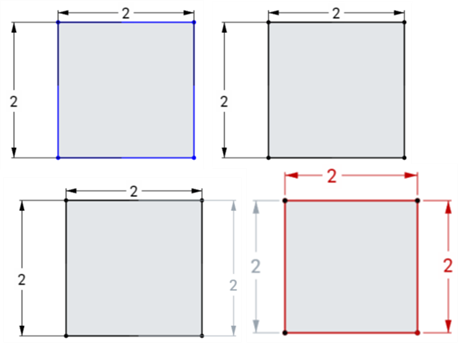
Onshape uses blue, black, and red to distinguish underconstrained, fully constrained, and conflicting geometry. The colour identifies solver status; it does not decide whether the chosen relationships are good design intent. Source: Onshape Help.
Find the remaining freedom instead of guessing#
The last free movement is usually the annoying one. A point can drift along a line. An arc can change radius while its endpoints remain coincident. A symmetric profile can still rotate. Adding random dimensions until the sketch stops moving is how duplicates and meaningless values enter the model.
Use a repeatable diagnosis:
- Drag the blue or underdefined geometry and watch the direction it moves.
- Hover or show the constraints attached to that entity.
- Decide whether the missing control is shape, size, orientation, or position.
- Add the relationship that matches the design intent, not the first dimension the toolbar offers.
- Change a driving dimension and confirm the sketch moves in the intended way.
- Regenerate the downstream feature and inspect the part, drawing, and affected interfaces.
Onshape's Constraint Manager can filter by type, internal or external mode, and driven, solved, or error status. It can also sort by constraint or entity and highlight the corresponding geometry. That is more useful than staring at a thicket of icons and clicking until something red disappears.
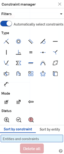
The Constraint Manager groups and filters the relationships that the solver is trying to satisfy. Source: Onshape Help.
Autodesk Fusion works through open, constrained, and fully constrained sketches and shows how to identify the missing control. Source: Autodesk Fusion on YouTube.
Overconstraint is usually an intent conflict#
An overconstrained sketch contains rules the solver cannot satisfy cleanly or rules that repeat a condition already established. The obvious case is conflict: one distance says 20 mm and another forces the same points 22 mm apart. Redundancy is quieter. A horizontal relation plus a zero-degree angle may describe the same condition twice.
When an edit turns the sketch red, begin with the newest rule. Ask which older relation already controls the same freedom. Convert a dimension to driven or reference status when it is meant to report a value rather than control it. Delete the duplicate, not a random relation that merely makes the warning go away.
External references deserve extra suspicion. A projected edge may have moved because an upstream feature changed. The local sketch then appears to fail even though the actual cause sits earlier in the model. Onshape distinguishes external and in-context constraints in its manager, which helps trace that dependency before somebody deletes the constraint and quietly changes the design.
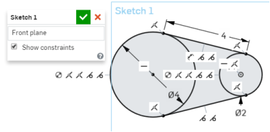
Conflicting relations are shown on a red background, making it possible to inspect the dependency before deleting it. Source: Onshape Help.
Fix is a tool, not a modeling strategy#
Fix has legitimate uses. It can hold imported sketch geometry, freeze a temporary layout, or preserve a traced reference whose original construction is unavailable. It is also the fastest way to make a sketch look finished while hiding why anything is where it is.
Use Fix deliberately and locally. Name or document why the geometry is frozen. If the feature will drive production geometry, replace the fixed coordinates with dimensions and relationships tied to functional references as soon as the intent is known.
The same warning applies to automatic fully-define commands. They can close the remaining freedom quickly. Review every added relation and dimension before treating the result as a maintainable model. A solver can make the equations determinate. It cannot tell whether a 37.428 mm coordinate should become an engineering requirement.
Split sketches before they become a dependency cupboard#
A single master sketch can control a product elegantly until every downstream feature, option, and interface is wired into it. Then changing one relation becomes like pulling a cable from the back of a crowded desk. Something important goes dark, and nobody is sure which plug did it.
Keep one sketch when the geometry shares one coherent design decision. Split it when different features have different lifecycles, planes, manufacturing purposes, or ownership. A mounting pattern, an enclosure outline, and a decorative vent may all appear in the same view while deserving separate sketches.
The cost of splitting is more references between features. The benefit is a smaller solver problem, clearer failures, and a model where the person changing the vent does not have to understand the mounting scheme. Use stable datums and named dimensions to connect the pieces rather than copying geometry until the sketches merely look aligned.
Constraints do not survive every handoff#
Sketch constraints are native model intelligence. A STEP or Parasolid export can carry precise B-Rep geometry, but it normally does not carry the original sketch relations, feature order, or named dimensions that created the shape. The receiver gets the result, not the recipe.
That matters for supplier work and CAD migration. If future edits depend on the constraint scheme, send the controlled native model when the commercial and technical process allows it. If the handoff must be neutral geometry, include drawings, PMI, or interface dimensions that state the important intent outside the lost feature tree.
The CAD version-control workflow applies here too. A fully constrained sketch in a working file is not automatically the released definition. The model, drawing, manufacturing export, and revision still need to point to the same approved state.
Fully constrained is necessary, not sufficient#
A sketch can be fully constrained and still be wrong. The hole pitch can be controlled to the wrong datum. The wall can be too thin. The slot can be centred beautifully in a part that does not assemble. The feature can rebuild while violating a tolerance, tool-access requirement, or supplier process.
Text-to-CAD makes this distinction especially important. A generated script or feature tree may satisfy the solver and create valid geometry without encoding the relationships a designer expects to revise. The text-to-CAD mechanism guide explains why geometric validity and design intent are separate problems.
Finish with two tests. First, change the driving values and confirm the sketch preserves the intended relationships without conflict. Second, inspect the resulting part against assembly, manufacturing, and drawing requirements. Solver status answers whether the rules close. Engineering review answers whether they are the right rules.
That is the standard I want from a sketch: no unexplained movement, no mystery dimensions, and no red icon waiting for the next Friday revision. Black geometry is pleasant. A model that changes without betrayal is the actual point.
Related articles
CAD Workflows
Direct vs parametric modeling: choose for the change
Use direct modeling for local edits to imported geometry, fast concepts, and changes whose intent is obvious from the existing faces. Use parametric modeling when dimensions, relationships, configurations, drawings, and future revisions must update predictably; most production workflows benefit from mixing both deliberately.
CAD Workflows
CAD version control: versions, revisions, and releases
CAD version control should preserve every useful design state while reserving revision labels for approved changes. Release one traceable package of the native model, drawing, BOM, and required exports so manufacturing can identify exactly what was approved.
Text-to-CAD
How text-to-CAD actually works
Text-to-CAD works by feeding a natural language prompt into a trained neural network that outputs a sequence of CAD operations (sketches, extrusions, fillets) rather than pixels or mesh triangles. The AI generates B-Rep geometry using learned patterns from datasets like DeepCAD's 170,000 parametric models.
Newsletter
Get new CAD articles in your inbox
Text-to-CAD guides, new tools, CAD comparisons, and practical tutorials.