

Sheet metal flat patterns: make the bends match the CAD
A flat pattern is only as trustworthy as the bend data behind it. Calibrate the material, tooling, and measurement method before a neat DXF becomes an expensive batch of wrong brackets.
Quick answer
Make a sheet metal flat pattern match the formed part by using bend data measured for the actual material, thickness, inside radius, tooling, and process. Enter that data as a K-factor, bend allowance, bend deduction, or bend table, then cut and form a test coupon and verify the result before releasing production DXF files.
The bracket comes back from the press brake with both holes exactly where the DXF put them and the finished flange 1.2 mm too short. The flat pattern looked tidy on the second monitor. The bend lines were clean. The operator has the calipers in one hand and the expression of somebody who has seen CAD make this promise before.
The fix is not to drag the flange until the next part happens to fit. A trustworthy flat pattern needs bend data for the actual material, thickness, inside radius, tooling, and forming process. Put those values into the sheet metal model as a K-factor, bend allowance, bend deduction, or bend table. Then cut and form a simple test piece and compare the measured result with the model before releasing a production batch.
The important bit is the loop between CAD and the brake. A generic K-factor can start a prototype. Shop-calibrated bend data is what makes the flat pattern a controlled manufacturing definition.
The flat pattern is a manufacturing model#
A folded sheet metal part and its flat blank describe the same part in two states. The CAD system has to account for material consumed through each bend when it moves between them. It cannot recover that behaviour from the finished outside dimensions alone.
Onshape's Sheet Metal Model help, updated October 9, 2026, keeps the folded model, flat pattern, and bend table synchronized. It offers K-factor, direct bend allowance, and bend deduction as calculation methods. That is useful automation, but the software still needs the right inputs.
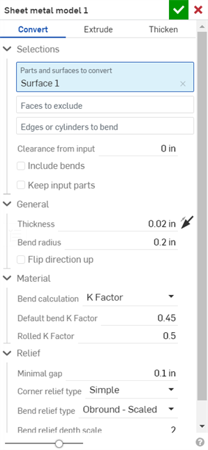 Onshape exposes thickness, bend radius, K-factor, and relief settings in the sheet metal model. The dialog can store a value; it cannot prove that value matches your brake. Source: Onshape Help.
The existing AI CAD for sheet metal guide explains why a solid that merely looks bent is not a real sheet metal model. This is the next problem. Even a proper sheet metal feature can unfold to the wrong blank when its bend data does not match the process.
Choose the calculation language#
The common methods describe the same bend from different directions.
| Method | What the CAD system stores | Useful when |
|---|---|---|
| K-factor | The neutral-axis location as a fraction of material thickness | A rule has been calibrated for a material, thickness, radius, and process |
| Bend allowance | The arc length of the neutral axis through the bend | The shop provides allowance values directly |
| Bend deduction | The amount subtracted from the sum of outside flange dimensions | Finished outside dimensions drive the drawing and inspection |
| Bend table | A controlled set of values indexed by thickness, radius, angle, or other shop rules | Several repeatable material and tooling combinations are in use |
SOLIDWORKS Design Help 2026 exposes bend tables, K-factor, bend allowance, bend deduction, and bend calculations in its Bends PropertyManager. Its K-factor page also supports K-factor tables, configuration-specific values, and material-based defaults. Different interfaces, same obligation: choose one controlled method and know what dimensions it assumes.
Do not mix methods halfway through a part unless the exceptions are intentional and documented. A default K-factor on the first bend, a hand-entered deduction on the second, and a supplier table on the third can produce a plausible flat pattern that nobody can reproduce six months later.
The arithmetic is simple; the input is the trap#
For a bend angle in degrees, SOLIDWORKS gives the K-factor form of the bend allowance as:
BA = (π × A / 180) × (R + K × T)Here BA is bend allowance, A is bend angle, R is inside bend radius, K is K-factor, and T is material thickness. SendCutSend's fabrication guide uses the same relationship and gives bend deduction as:
BD = 2 × (R + T) × tan(A / 2) - BAConsider an illustrative 90-degree bend in 2 mm sheet with a 2 mm inside radius and a K-factor of 0.40. The calculation gives a bend allowance of about 4.398 mm. The outside setback is 4 mm on each side, so the bend deduction is about 3.602 mm. If the required outside flange dimensions are 50 mm and 30 mm, the calculated flat length is 76.398 mm, not 80 mm.
Those numbers are worked arithmetic, not a tested recipe. Change the measured thickness, radius, tooling, angle convention, or K-factor and the blank changes. If the drawing dimensions are to tangent points or inside faces rather than outside mould lines, the setup changes as well. A clean answer from a calculator can still be the answer to the wrong dimensional question.
SendCutSend works through bend allowance and deduction on a fabricated channel. Its published material values describe its process, not every brake and tool combination. Source: SendCutSend on YouTube.
Calibrate one controlled bend first#
The safest test piece is deliberately boring. Use a strip or angle coupon with one bend, a known blank length, generous flange dimensions, and marks or holes far enough from the bend not to distort. The goal is to isolate the bend rather than prove how clever the part geometry can be.
Record the conditions before forming it:
- Material grade, temper or condition, nominal and measured thickness, and grain direction.
- Intended bend angle, inside radius, and whether the process is air bending, bottoming, folding, or another controlled method.
- Punch radius, die opening, and the exact machine or tool set when those matter to repeatability.
- Blank dimensions, bend-line convention, and the faces or mould lines used for finished measurements.
- Inspection method and when the part is measured after forming.
Cut the coupon, form it on the intended tooling, let the part settle, and measure the finished angle and flange dimensions using the same convention the drawing will use. Work back to the bend deduction or allowance that makes the measured part agree with the required result. Enter that value in a test rule, regenerate the flat, and make a second piece. One lucky bracket is not a bend table.
Protocase's bend-radius tables make the tooling dependency visible. The company publishes different radii and minimum bend dimensions for its stocked materials, thicknesses, folders, and press-brake tooling. That is supplier-specific data, which is exactly why copying one universal K-factor from a forum is such a weak release process.
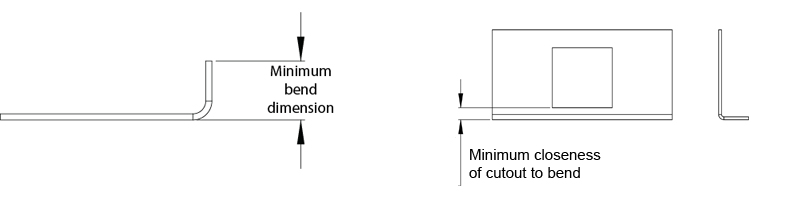 Tool geometry constrains the flange and feature distances that can be formed. Source: Protocase bend radii and minimum bend sizes.
Build a bend table, not a magic number#
A single K-factor may work across a narrow family of parts made from the same stock on the same setup. It should not quietly become a company constant for steel, stainless, aluminium, every gauge, and whichever die happens to be free after lunch.
A useful internal table should identify, at minimum:
- material specification and condition
- thickness range actually measured
- inside radius or the tooling that produces it
- bend angle or validated angle range
- forming process and machine or tool family
- K-factor, bend allowance, or bend deduction used by the CAD system
- coupon revision, sample count, measured result, and approval date
Keep supplier rules separate when different fabricators use different tooling. If Supplier A asks for a model built to its published bend data and Supplier B unfolds parts in-house, one shared mild-steel-default rule hides a commercial and technical difference.
The table also needs ownership. A new material batch, a different die opening, a coating change, or a revised inspection convention may justify another coupon. That does not mean recalibrating every morning. It means the stored value has a scope somebody can explain.
Onshape's official tutorial shows a proper sheet metal angle-bracket workflow. It demonstrates the modeling tools, not a press-brake qualification test. Source: Onshape on YouTube.
Keep the flat, table, and drawing tied together#
Onshape lets each bend be edited in its sheet metal table while the 3D and flat views update together. That makes local exceptions visible, provided the team does not treat the table as disposable interface clutter.
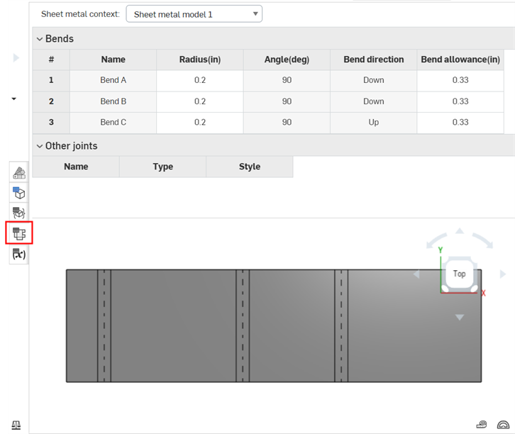 The useful relationship is not just folded versus flat. The bend table records how each joint is interpreted. Source: Onshape Sheet Metal Table and Flat View.
Give the material rule and bend table a revision just like the drawing and native model. If the bend data changes, regenerate the flat pattern rather than stretching yesterday's DXF. Record which rule produced the released blank, especially when the supplier receives both the folded STEP and the flat file.
Features near bends need their own check. Protocase distinguishes minimum flange distance from minimum hole distance because tooling support and local deformation are different problems. A flat pattern can have the correct total length while a slot beside the bend still pulls into an oval or a flange cannot sit across the die.
The sequence matters too. Two bends that are individually feasible can make the second bend inaccessible after the first is formed. CAD can show the finished shape and sometimes simulate forming, but the brake operator still needs a workable order, tool access, and handling plan.
Treat the DXF as released manufacturing data#
The DXF exported from the flat pattern is not an informal picture. It is normally the geometry that drives the laser, punch, or waterjet before bending. Check it with the same suspicion you would apply to a drawing.
Onshape's flat-view documentation exports the flat pattern as DXF or DWG and exposes options for versions, spline handling, z-height, and layer assignment. Those options can change what the receiving CAM system sees.
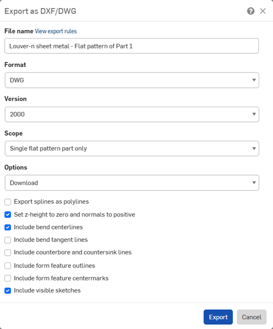 Flat-pattern export has format, spline, layer, and geometry options that belong in the release check. Source: Onshape Sheet Metal Table and Flat View.
Before release:
- Regenerate the flat from the approved folded model and approved bend rule.
- Confirm material, thickness, grain direction, bend direction, quantity, and revision in the drawing or job data.
- Inspect the flat for overlaps, missing reliefs, short flanges, and features too close to bends.
- Export once, reopen the exact DXF in the receiving CAM or an independent viewer, and check units, scale, duplicate entities, splines, layers, and overall dimensions.
- Compare the reopened blank with the CAD flat pattern and confirm that bend lines are included or omitted according to the supplier's process.
- Keep the DXF, drawing, model, and bend-table revision together in the release package.
The calculations and product behaviours in this guide come from the current sources linked above. I did not cut a coupon, run a press brake, inspect a formed part, or validate a production batch for this article. The worked dimensions are illustrative, and supplier tables must be treated as process-specific unless the supplier says otherwise.
A flat pattern is not trustworthy because it unfolds without an error icon. It is trustworthy when its bend assumptions match a known process, a formed sample agrees with the intended dimensions, and the released DXF can be traced back to both. That is less glamorous than watching the model fold on screen. It is also how the holes end up where the drawing promised.
Related articles
Text-to-CAD
AI CAD for sheet metal: flat patterns and bend allowances
AI-generated CAD models cannot handle sheet metal design. Text-to-CAD tools don't understand bend radii, K-factors, bend allowances, minimum flange lengths, relief cuts, or flat pattern unfolding. AI might generate something that looks like sheet metal in 3D but can't be fabricated. Use your CAD tool's sheet metal environment instead.
CAD Workflows
Text-to-CAD file formats: STEP, Parasolid, STL, 3MF, and more
Use the native CAD file when both people use the same system, Parasolid when both systems share that kernel, and STEP AP242 for the safest neutral engineering handoff. Use 3MF for printing, glTF or GLB for browser review, and DXF for flat 2D profiles.
CAD Workflows
CAD version control: versions, revisions, and releases
CAD version control should preserve every useful design state while reserving revision labels for approved changes. Release one traceable package of the native model, drawing, BOM, and required exports so manufacturing can identify exactly what was approved.
Newsletter
Get new CAD articles in your inbox
Text-to-CAD guides, new tools, CAD comparisons, and practical tutorials.