

FEA mesh convergence: when is the result trustworthy?
A smooth stress plot can still be controlled by element size. Refine the mesh around the engineering decision, track the same result across several solves, and separate a converging hotspot from a mathematical singularity.
Quick answer
An FEA result is mesh-converged when a decision-relevant quantity at a fixed location changes by less than a justified tolerance over successive mesh refinements. Use at least three meshes, keep loads and boundary conditions unchanged, refine locally where gradients are high, and do not treat a peak stress that rises without limit at a point load or sharp corner as a physical material stress.
The first solve finishes before the coffee has gone cold. The bracket is blue everywhere except for one angry red pixel at the fixed edge, and the legend says 312 MPa. You halve the element size, wait while the workstation fans spool up, and get 468 MPa. Another refinement gives 691 MPa.
That is not the software gradually discovering a stronger bracket. It may be the model telling you that the reported peak has no finite answer.
An FEA result is useful only when the quantity behind the design decision is insensitive enough to further discretisation. Run a mesh-convergence study on a fixed model, compare the same displacement, reaction, strain energy, or stress measure over at least three successively refined meshes, and define the acceptable change before admiring the colour plot. If a local maximum stress keeps climbing while nearby stress and global displacement settle, investigate a stress singularity instead of reporting the largest number as material truth.
This is a source-based verification workflow with illustrative numbers. I did not run these meshes, qualify a solver, or approve a real component. Loads, material behaviour, contacts, geometry, element formulation, and acceptance criteria still need an analyst who understands the part.
Solver completion is not mesh convergence#
A finite element model replaces continuous geometry with a finite set of elements and nodes. The solver returns a solution for that discrete model. A green tick therefore means the equations for that particular model were solved to the requested numerical criteria. It does not prove that the mesh represents the underlying physical problem closely enough.
NAFEMS calls mesh convergence one of the most overlooked influences on accuracy. Its practical definition is simple: change the mesh size and check whether the result stops changing materially. NAFEMS recommends a convergence curve with at least three runs unless two different mesh densities already return the same result.
The two ideas are easy to mix up:
| Check | What changes | What a pass means |
|---|---|---|
| Solver convergence | Iterations within one analysis | The discrete equations reached the solver's stopping criteria |
| Mesh convergence | Element size or polynomial order across analyses | The selected result is becoming insensitive to discretisation |
| Model validation | Prediction versus trusted physical evidence | The model represents the real behaviour closely enough for its intended decision |
A solve can converge numerically on a bad mesh. A mesh can converge neatly around the wrong load case. A model can match one test for the wrong reason. Keep those claims separate, especially in a release meeting where one green icon has a strange ability to end difficult conversations.
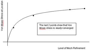
NAFEMS illustrates convergence by plotting a fixed result quantity over several mesh densities. Source: The Importance of Mesh Convergence.
Choose the result before changing the mesh#
"Maximum stress" is usually a poor convergence target on its own. It can jump from node to node, respond to averaging settings, and be dominated by a point load, fixed vertex, contact edge, or ideal sharp corner. Choose outputs that correspond to the engineering question and identify exactly where and how they will be read.
For a mounting bracket, a useful set might include:
- displacement at the loaded interface;
- reaction force at each support;
- strain energy for the whole model;
- average or path stress through a named section;
- local stress at a stable location away from a suspected singularity;
- contact pressure or bolt force when those control the design.
Keep the model definition fixed between runs. That means the same geometry, materials, loads, contacts, constraints, result locations, element formulation, and solver options. If you change the fillet radius during the same series, you are studying geometry and mesh together. The new result may be better, but it is no longer a clean convergence comparison.
Use named selections, probes, paths, or coordinate-based locations that survive remeshing. Clicking whichever red node happens to be hottest in each run is not comparing the same thing. It is letting the legend choose the experiment.
Build a convergence table you can audit#
Start with a mesh that captures the geometry without producing obviously collapsed or badly distorted elements. Solve it, reduce the characteristic element size in the region of interest, and repeat. NAFEMS says local refinement is valid when the refined region and its transition are arranged so the surrounding coarse mesh does not corrupt the result of interest.
Record more than the colour scale:
| Run | Local element size | Elements | Tip displacement | Section stress | Peak nodal stress |
|---|---|---|---|---|---|
| 1 | 6.0 mm | 18,400 | 0.82 mm | 142 MPa | 310 MPa |
| 2 | 3.0 mm | 51,900 | 0.88 mm | 159 MPa | 475 MPa |
| 3 | 1.5 mm | 146,000 | 0.90 mm | 164 MPa | 720 MPa |
These numbers are an illustration, not test data. They show three different stories. Tip displacement changes by about 2.2% between the last two runs. Section stress changes by about 3.0%. Peak nodal stress rises by more than 50% and shows no sign of settling.
For each chosen result, calculate the change against the newer value:
relative change = |new result - previous result| / |new result| × 100%The stopping tolerance belongs to the decision, not to a universal internet rule. A preliminary stiffness comparison may tolerate a few percent. A fatigue assessment near a weld or a proof for a safety-critical component may need a stricter method, code-specific treatment, test correlation, and specialist review. State the threshold before the final solve so it cannot be chosen merely because the last run took forty minutes.
Ansys How To demonstrates the controls used to create line, surface, and solid meshes. It is product instruction, not independent evidence that a particular model is accurate. Source: Ansys How To on YouTube.
Refine where the physics changes quickly#
Blanketing the entire model with tiny elements is an expensive way to avoid thinking. High gradients usually sit around holes, fillets, contacts, load introduction, section changes, and other local details. Refine those regions while keeping a sensible transition into the coarser surrounding mesh.
Ansys's meshing overview recommends local sizing, refinement, and other controls rather than one global size for every feature. It also separates geometry preparation from meshing: manufacturing detail that has no effect on the result may be removed, while geometry that carries load must remain.

Ansys uses this gearbox casing to show a structural finite element mesh. The image demonstrates discretisation, not a validated stress result. Source: The Fundamentals of FEA Meshing for Structural Analysis.
That CAD preparation needs restraint. Removing a logo from a loaded housing may save elements without changing the load path. Removing a small fillet beside the critical notch can create a zero-radius corner and destroy the very stress result you meant to improve. The defeaturing workflow is useful here, but its interface-first logic becomes physics-first logic for simulation.
Element type matters too. Ansys notes that hexahedral elements can achieve accurate results with fewer elements in suitable geometry, while tetrahedral meshes are often easier for complex shapes. That is not a licence to declare every hex mesh superior. Element order, aspect ratio, distortion, contact formulation, through-thickness resolution, and the result being measured all affect the comparison.

Ansys shows a general frame mesh with extra attention around welded connections. Local refinement should follow the region of interest, not decorate the whole model with equally small elements. Source: The Fundamentals of FEA Meshing for Structural Analysis.
A rising peak can be the correct warning about the wrong model#
A linear-elastic model with a point load, a point restraint, a perfectly sharp re-entrant corner, or an abrupt idealised boundary can contain a mathematical singularity. As elements shrink toward that location, the calculated local stress rises instead of approaching a finite value.
Ansys's stress-singularity guidance says common causes include point loads and restraints at one node, linear-elastic material assumptions, and sharp CAD corners without a fillet. It also makes the important qualification: a local singularity does not automatically invalidate every result. Displacements and stresses away from the singular point may still converge.
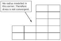
NAFEMS shows an internal corner with no modelled radius. Refining this ideal corner drives the elastic peak upward rather than toward a physical stress. Source: The Importance of Mesh Convergence.
Diagnose the hotspot instead of deleting it from the screenshot:
- Plot the peak stress over successive local refinements.
- Track displacement, reaction, strain energy, and nearby stress at fixed locations.
- Inspect whether the peak sits on a point load, point restraint, contact edge, crack tip, or sharp corner.
- Ask whether the real part has a radius, load patch, washer, contact area, plasticity, weld profile, or other physical detail omitted from the idealisation.
- Change the model only when the physical problem justifies the change, then begin a new convergence series.
If the real part has a specified minimum fillet, model that radius and place enough elements around it to resolve the gradient. If the load enters through a bearing, bolt head, pad, or contact area, represent that mechanism rather than feeding the entire force through one convenient node. If the singularity is inherent to the idealisation and the design decision lives away from it, define an exclusion zone or use a code-approved stress-linearisation method and explain why.
Do not simply cap the legend or quote an averaged stress without recording the method. Cosmetic calm is not verification.
Ansys How To demonstrates mesh control and geometry changes around a stress concentration. It is a vendor tutorial, not proof for the illustrative bracket above. Source: Ansys How To on YouTube.
Adaptive refinement still needs an engineering target#
Adaptive methods can reduce manual mesh work. They refine elements or increase approximation order where an error measure indicates that more resolution is needed. SOLIDWORKS Simulation Tutorials 2026 includes both h-adaptive and p-adaptive methods and shows convergence graphs for a plate with a known stress concentration.
The automation is useful, but it does not choose the right question. An adaptive routine can spend enormous effort chasing a singular peak if the target is poorly defined. Review what quantity controls refinement, where the error estimate applies, whether contact changes between passes, and what final tolerance stopped the process.
For a large assembly, a submodel may be more honest. Solve the global structure for load transfer and displacement, then drive a separate detailed model of the critical joint or fillet. Ansys lists submodelling as one way to refine the region near a singularity without making the whole model computationally expensive. The cut boundary must sit far enough from the local disturbance, and the transferred displacement field still needs checking.
Mesh independence does not rescue bad physics#
A beautiful convergence curve can make a wrong model repeatable. Before calling the result trustworthy, review the assumptions that do not improve when elements get smaller:
- Are loads distributed through the surfaces and hardware that carry them in the real assembly?
- Do constraints permit the rigid-body movement and compliance the physical support permits?
- Are contacts, friction, bolt preload, gaps, and interference represented at the required fidelity?
- Does the material model cover yielding, plasticity, temperature, orthotropy, or rate effects that matter?
- Is a shell, beam, or solid formulation appropriate, with enough elements through thickness where bending or contact requires them?
- Does the geometry contain the radii, weld toes, holes, or thickness transitions that control the result?
- Is the acceptance quantity linked to a material allowable, code rule, fatigue method, or physical test that actually matches it?
Mesh convergence is verification of the discretisation. It is not validation of the whole engineering model. That distinction is less exciting than an animation, but it is the difference between a calculation that is repeatable and a prediction that deserves trust.
Keep the evidence with the released revision#
A reviewable convergence record does not need to become a thesis. Save the model revision, software and solver version, element type and order, mesh controls, element and node counts, result locations, convergence table or graph, acceptance threshold, and treatment of singular regions. Include enough images that another analyst can see where the fine mesh sits and where each result was taken.
Then connect the analysis to the engineering revision. A convergence study on Rev C is not evidence for Rev D after somebody thins the rib, changes the fillet, or moves the load face. Rerun the affected checks and keep the older record as history.
The result I trust is not the prettiest contour. It is the one that changes little when the relevant mesh is refined, still makes sense when reactions and deformed shape are checked, and has an explicit answer for every singular red speck. The colour plot can come to the review. The convergence evidence gets the chair.
Related articles
Text-to-CAD
AI topology optimization: generative design's older cousin
AI topology optimization uses algorithms (not text prompts) to find optimal material distribution for given loads and constraints. Unlike text-to-CAD, it produces structurally validated geometry. Available in Fusion 360, nTopology, Altair Inspire, and ANSYS. Output is often organic and hard to manufacture without additive processes.
CAD Workflows
How to simplify a CAD model before sharing it
Simplify a CAD model for sharing by creating a separate derivative from the released master, keeping only the interfaces, envelopes, datums, and properties the recipient needs. Remove internal parts, design history, and unnecessary metadata, then reopen the exported file and validate fit, clearance, motion, and revision identity against the master.
CAD Workflows
CAD version control: versions, revisions, and releases
CAD version control should preserve every useful design state while reserving revision labels for approved changes. Release one traceable package of the native model, drawing, BOM, and required exports so manufacturing can identify exactly what was approved.
Newsletter
Get new CAD articles in your inbox
Text-to-CAD guides, new tools, CAD comparisons, and practical tutorials.